![]()
Ball Spin Detection Theory
Note : This page will include numerous real spin detection shot examples within the next few days and weeks
Work on this page is being done every day, so please check back for updates.
This page was last updated on: 02/12/2024 8:29 am
![]()
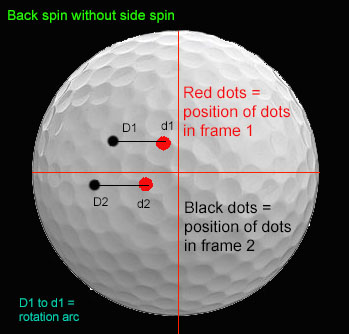
Measuring Ball Spin from an overhead ceiling mounted camera
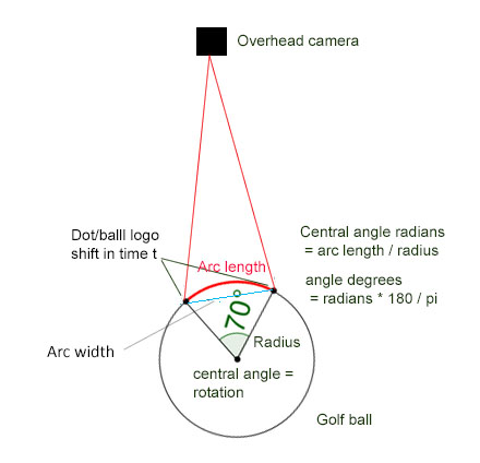
Measuring spin from an overhead camera using spin dot balls as reference and measuring a partial rotation between frames.
Two measurements are required:
1. Vertical rotation back spin
2. Horizontal rotation side spin
From these two measurements a Total spin can be calculated
Total spin ?
Total spin is the vector sum of back and side spin rates which can be calculated as follows:
Total spin = square root of (back spin squared + side spin squared)
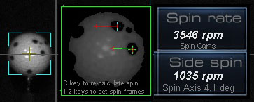
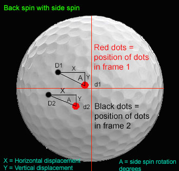
Rotation and side spin is calculated by comparing x and y co-ordinate spin dot deviation positions between frames on the ball.
Perspective mapping
In order to determine the amount of rotation, co-ordinate points on the ball as seen by the camera have to be transformed to real co-ordinate points.
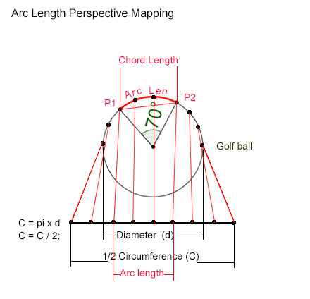
Each point co-ordinate as seen from the overhead camera is mapped to the real circumference of the ball in both the x and y directions.
Whereby x co-ordinates are used to determine ball back spin and y co-ordinates are used to determine side spin (+ or -)
Essentially this is just a distance correction factor based on the point's distance from the center of the ball.

An additional arc length correction factor based on the dot's distance from the center line also has to be applied.
The real arc length of the two points can then be calculated.
Knowing the arc length and the radius of the ball, the arc central angle can be calculated.
This arc central angle is the back rotation in degrees (or radians) for a given time between the two frames (1 ms) and from this the back spin rate can be calculated.
Deriving arc length from 2 dot points
Pc = C/ d
(PC = Perspective Correction, C = ball circumference / 2, d = ball diameter)
pd1x = dot1x*Pc
pd2x = dot1x*Pc
(pd1x, pd2x = perspective corrected dot x co-ordinates)
Calculate off-center correction
chordlen1 = 2 × √(r2 − d2)
chordlen2 = 2 × √(r2 − d2)
(r = ball radius, d = y distance dot from ball center line)
offCenterFactor1 = chordlen1 / ball diameter
offCenterFactor2 = chordlen1 / ball diameter
Cdx1 = pd1x * offcenterFactor1
Cdx2 = pd2x * offcenterFactor2
ArcLen = Cdx1 - Cdx2
Deriving rotation from arc length
Calculate degrees of rotation given Arc length and ball radius
Use the formula: CA (Central Angle) = ArcLen * 360 / 2 π r
Calculate spin rate
Given time t (the time between 2 frames) and the amount of rotation within this time, calculate spin rate in rpm
Use the formula: Spin rate rpm = (r/t) / 6
where r = degrees of rotation
and t is the time in which the rotation occurs.
Divide by 6 to get RPM
Spin rate in RPM = w / 6
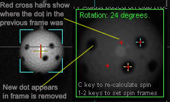
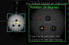
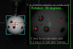
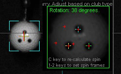
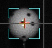
Note that only well defined and spaced spin dot balls can be used ( as shown above).
And that camera exposure time (i.e. shutter speed) has to be set at or below 150 micro seconds and frame set to 1500 fps
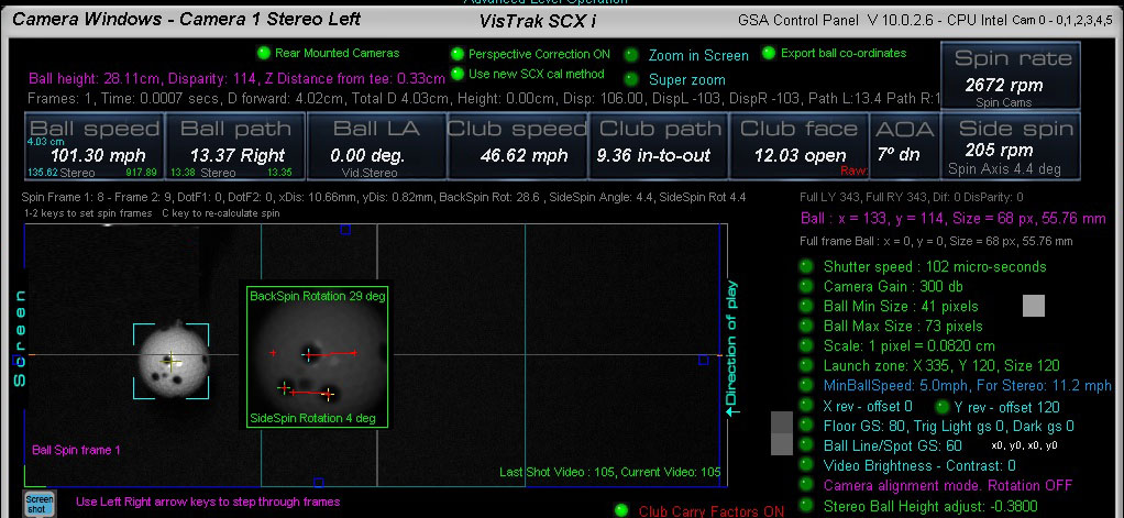
Note that the "Ball line/Spot GS" (Gray Scale) may ( depending on your lighting )
have to be adjusted up or down in order to detect the ball spin dot or ball logo.
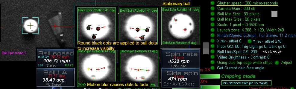
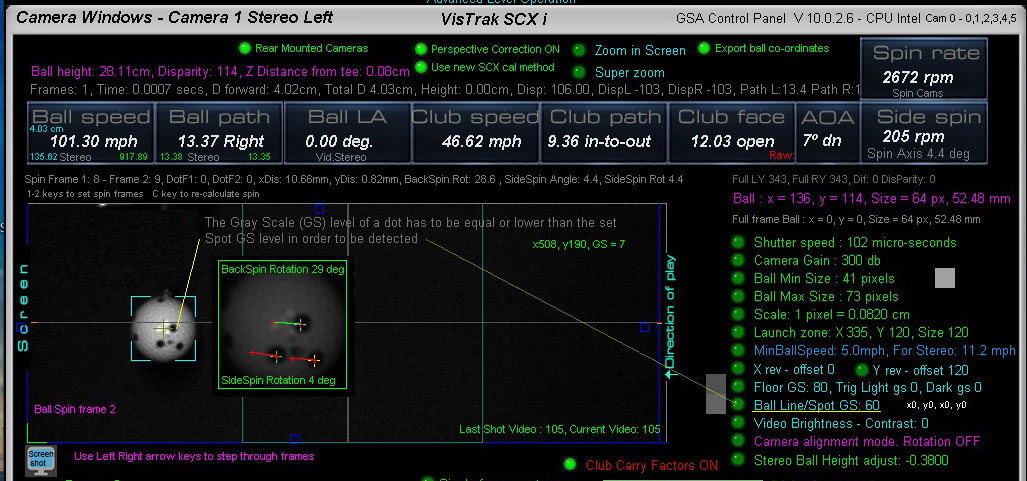
The above image (from a customer shot video) shows the issue with longer exposure times
and out of focus lenses when attempting to detect ball spin dot markings.
Exposure times need to be under 150 us to reduce motion blur caused by the ball traveling at high speeds.
Nether-the-less, if increasing the Ball Spot GS (gray scale) to 200,
then even out of focus and blurry ball dots can be detected.
Today's CP version also features improved ball spin frame detection by attempting to find 2 adjacent
ball images that have at least 3 dots on them instead of just 2.
Coming later..
1. Real shot examples showing verifiable side and back spin rates
2. Spin rate comparisons with the other launch launch monitors
New Ball Spin detection using the ball logo
for overhead SCX and Eagle systems
You can now select the option "Spin line / Logo on ball" to measure ball spin for overhead camera systems (i.e. SCX and Eagle).
As the logo will not always be visible in the frames, the system now automatically scans for 2 adjacent fames showing the ball logo
in all the 16 ball speed frames.
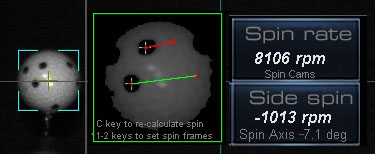
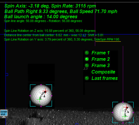
Spin axis and side spin
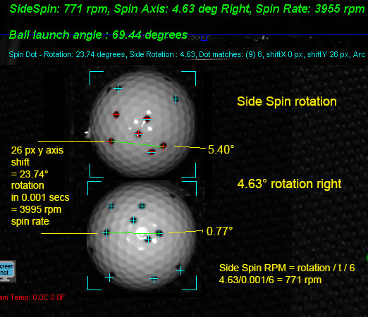
As we all know, there's no such thing as side spin but the camera does see horizontal rotation (side spin) as well as vertical rotation (back spin).
As the camera sees the two 2D images of the ball, it would look like the ball is rotating in 2 directions at the same time but that is only due to the spin axis being tilted.
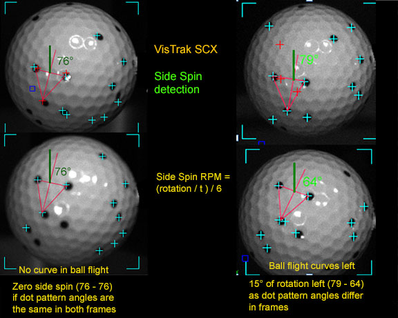
Camera tests revealed that as long as the ball is struck square to the club path (no matter if path is straight, in-to-out or out-to-in), then no side spin or spin axis tilt is imparted on the ball.
If club face differs from club path, then side spin and axis tilt can be detected.
Spin axis
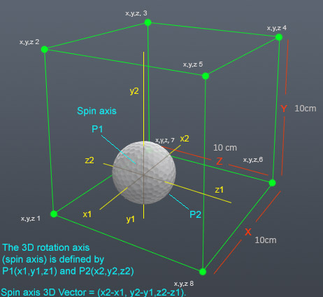
As ball spin axis is 3 dimensional, it cannot be shown as a simple number of degrees.
in order to actually show spin axis, you'd have to calculate a 3D vector which the average golfer wouldn't easily comprehend.
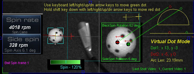
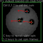
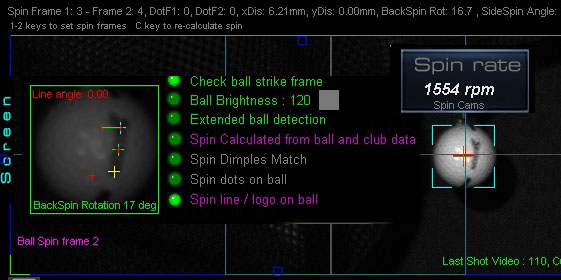
Virtual spin dots are used to test the spin detection method.
In the camera panel, Select a frame with a ball shown in it.
Select spin dot or logo on ball spin method.
Press the V key on your keyboard to go to Virtual Dot Mode
Use arrow keys to move dots around on the ball
The dots can be moved around anywhere on the ball image
and the resulting back and side spin rates - based on their co-ordinates - will be automatically shown.
New Ball Spin detection using the ball logo
for overhead SCX and Eagle systems
You can now select the option "Spin line / Logo on ball" to measure ball spin for overhead camera systems (i.e. SCX and Eagle).
As the logo will not always be visible in the frames, the system now automatically scans for 2 adjacent fames showing the ball logo
in all the 16 ball speed frames.
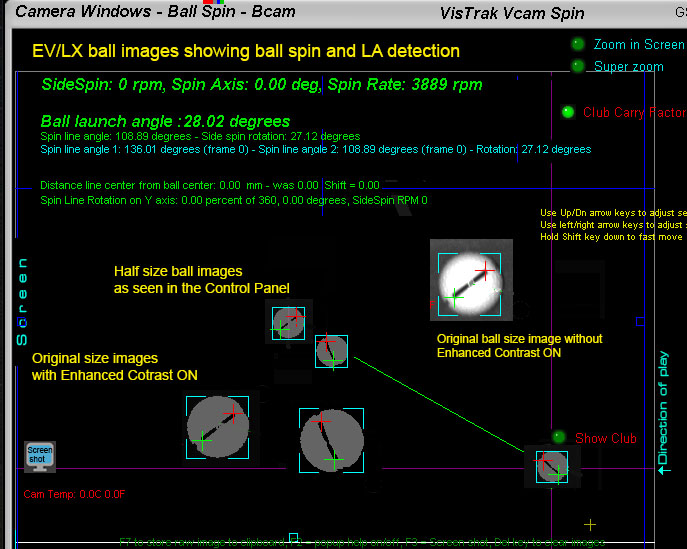
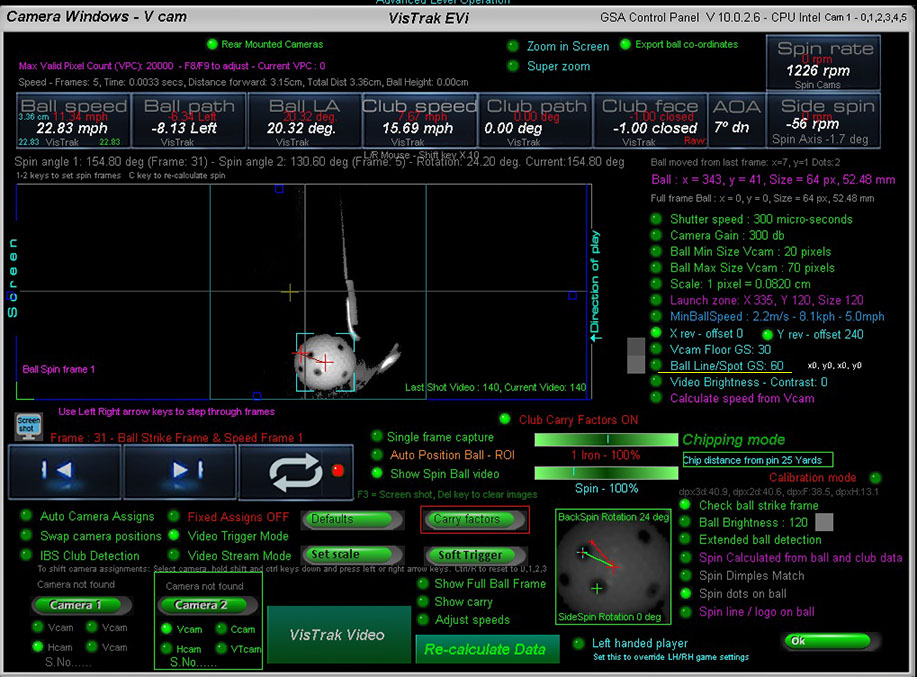
VisTrak EVi Ball Spin Detection
Ball Spin Detection from the Side camera
![]()
Using the ball logo or line
When the EVi or LX Vcam is placed close to the ball (i.e within 12 to 16 inches),
the camera detects ball spin rate using either the ball logo or ball spin dots.
![]()
Using balls with spin dots on them
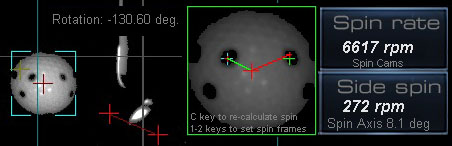
The Vcam with EVi and LX systems view the ball from the side.
Rotation - when using spin dot balls - is calculated around the center of the ball between frames
Note that the "Ball line/Spot GS" (Gray Scale) may have to be adjusted up or down in order to detect the spin dot or ball logo/line.
![]()
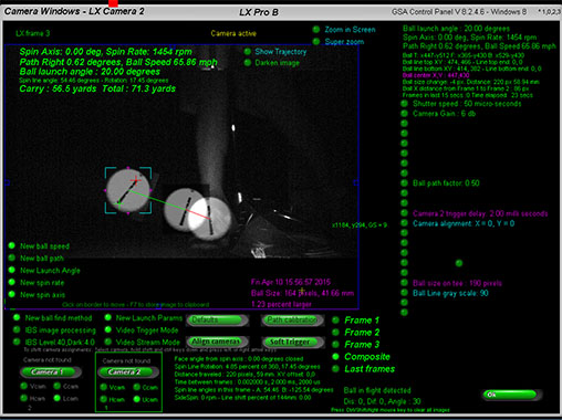
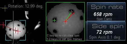
EV Ball Spin Detection from the overhead camera
Ball spin can also be measured from the EV overhead camera
Rotation and spin axis is calculated by comparing x and y spin dot deviation positions between frames
![]()
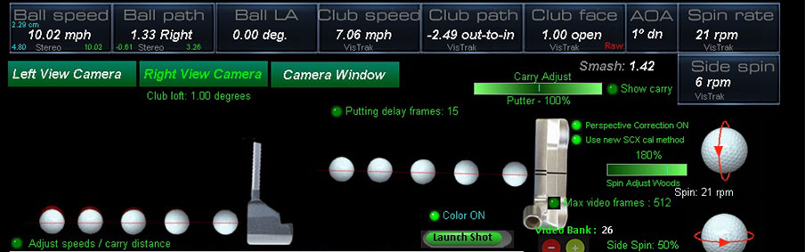
Ball spin for Putts
Measured ball spin when putting is done without the requirement to use ball markings.

![]()

![]()
 Home
Home Products
 Cameras
 Software
 Enclosures
 ProTee
 E6 Courses
 Business
 Tech News
 View Cart