![]()
SCX Stereo Camera Calibration
Note that all below instructions assume that you are using CP version 10.0.4.4 or higher
available as of 01/26.2024
Please note: Other than scaling, calibration is only really intended for fine tuning.
If you are experiencing major ball carry discrepancies, then the cause most probably lies elsewhere.

In this case, check the above link.

Click the above button to see an easy and fast SCX calibration method
![]()
What is stereo camera calibration?
As each individual camera installation will be slightly different,
(i.e. cameras are mounted at different heights, different spacing, off-line and slightly skewed)
the main objective is to correct the factory set default calibration tables so that they match the particular users camera installation.
There are 4 parts to the calibration process
1.
Conversion of stereo camera disparity values to precise ball height off ground levels
2.
Camera alignment so that both cameras are tracking the ball in-line
3.
Camera perspective correction
4.
Scaling
i.e. converting distances measured in pixels - as the camera sees them - to real world distances mesured in cm
This page is mainly concerned with Disparity Conversion and Perspective correction.
Camera alignment instructions are dealt with on another page

Click above button to read more...
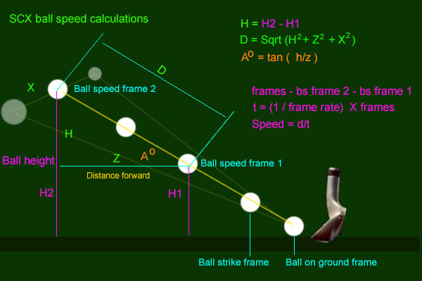
Scaling
The scaling factor is used to convert distances measured in image pixels (as the camera sees them)
to real world distances measured in cm.
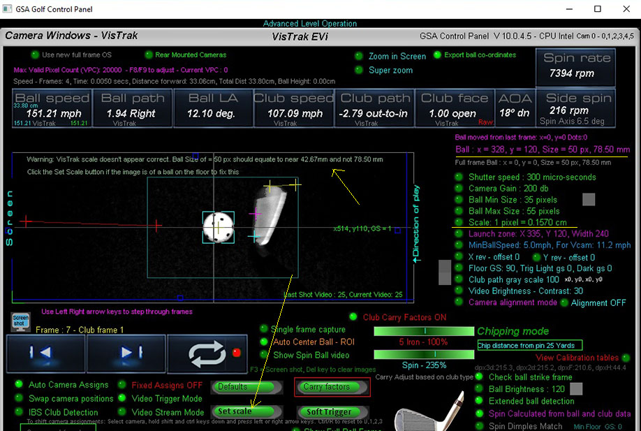
As a reference, the fixed diameter (42.67mm) of a golf ball is used.
In the above example, the ball size was measured at 50 pixels but the scaling factor of 0.1570 falsely converted the ball size to 78.50mm and not 42.67mm.
In this case, all distances will appear to be too long and thus ball and club speeds will be too fast
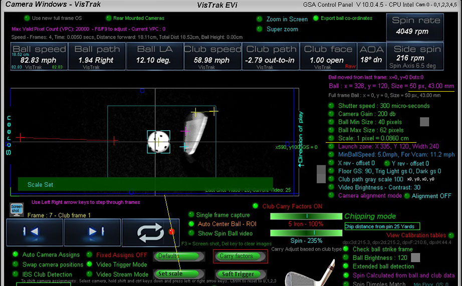
After setting the scaling factor correctly, ball and club speeds are correctly calculated
To set the scaling factor, place a ball on the mat and click the soft trigger in camera 1 panel.
Ensure that the ball has been correctly detected (as shown above with the aqua blue box lines around it)
and then just click the "Set Scale" button.
The scaling factor is then stored and shouldn't require any more adjustments.
Disparity Conversion Calibration
Conversion of stereo camera disparity values to precise ball height off ground levels
(see below for an explanation of the term Disparity)
Note that the cameras are already calibrated with basic settings.
If you would like to re-calibrate the cameras, proceed as follows:
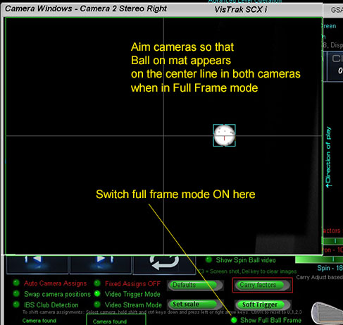
Before starting, ensure cameras are aimed correctly as shown above.
![]()
Virtual Ramp Auto Calibration
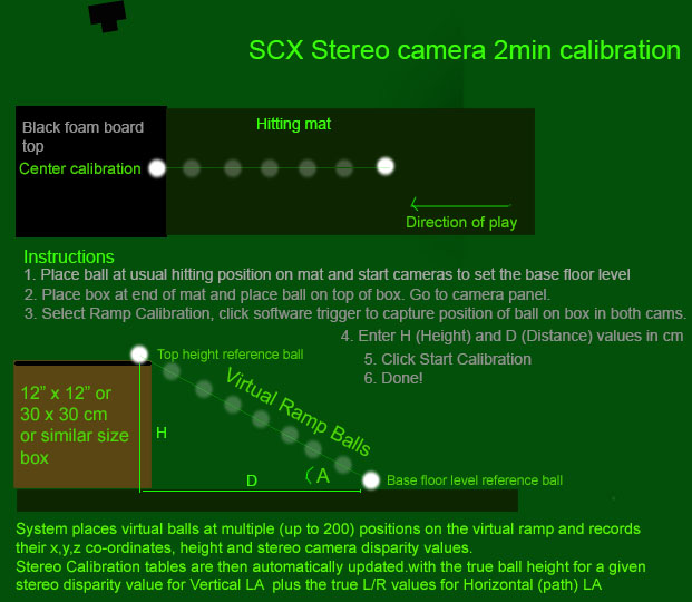
Method
This method requires 2 golf balls and a box
As the virtual ramp angle is fixed, the height of the ball for any given position on the ramp can be precisely calculated.
As virtual balls are placed down the ramp, their positions on the ramp and thus precise height can be calculated.
The disparity value for the virtual ball's position on the ramp is used as an index into the "Disparity to Height" conversion table.
![]()
Instructions:
Step 1.
Place ball on mat in the usual hitting position and click the "Start/Stop VisTrak" button to set the base floor level.
Wait until you see the message " ball detected, waiting for swing"
Step 2.
Go to the camera panel and select camera 1.
Place a second ball on a darkened box around 30 cm (12inches) high
and place the box 30 cm ahead of the ball on the mat directly ahead.

Foam board is ideal for covering the box to keep it dark
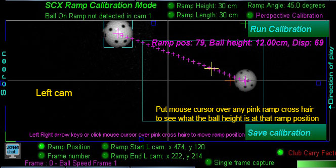
Step 3.
Click the "Soft Trigger" button to grab a frame of the ball.
Try to position the ball so that it appears at the top of the image as shown above
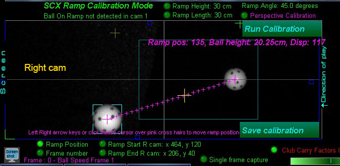
Step 4.
Switch to camera 2 and click the "Soft Trigger" button again to grab a frame of the ball.
Try to position the ball so that it appears at the bottom of the image as shown above.
After positioning, you should check the ball position in camera again.
The objective is to get both balls equally spaced apart in both cameras.
Running the cameras in Video Stream Mode helps here.
Step 5
Click the "Run Calibration" button
Step 6
Click the "Save Calibration" button
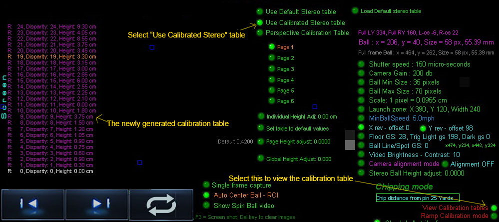
The calibration generates a new Disparity to Height" conversion table.
![]()
Testing the Calibration
Testing requires that the ball be placed at certain known heights off the ground
and manually comparing the known height to that in the disparity table.
Instructions:
Place the ball on a dark non reflective object of a known height
(anywhere from 2 to 20 cm high) and click the Soft Trigger button in both cameras 1 and 2 to grab new frames of the ball.
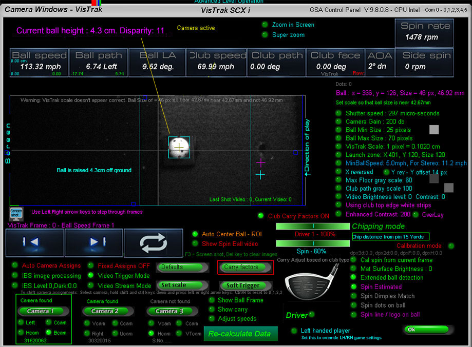
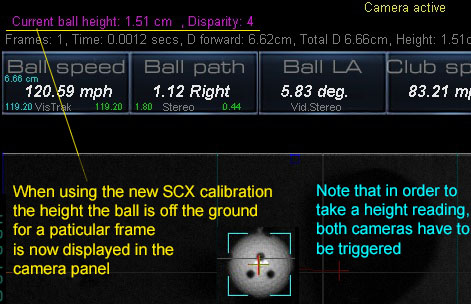
If the calibration is perfect then the "Current ball height" shown at the top of the panel should be the same as the actual ball height
In the above example, the ball was placed on a rubber stand 4.3 mm high.
If the ball height shown does not correspond to the actual height of the ball,
then the stereo "disparity to height" table has to be adjusted.
Adjusting the "Disparity to Height" table
Switch the "Calibration Mode" ON to see how the stereo "Disparity" value is converted to ball height via the Disparity-to-Ball Height table.
Note: click the "Load default stereo table" beforehand.
The disparity for the "Soft Trigger" frames is displayed in white text.
Select the "Global Height Adjust" option and use the PC's up/down arrows keys
until the Ball Height shown at the top left side of the screen corresponds to the actual ball height off the ground.
Note that when adjusting this, all other height values will automatically adjust.
You can also adjust the height for a particular disparity individually using the Individual "Height Adj." option.
Note that the current selected row for this is displayed in Orange text.
Use the up/down arrow keys to select the row when the options "Global Height Adjust" and "Height Adj." are off.
Click anywhere in the screen to switch the active options OFF.
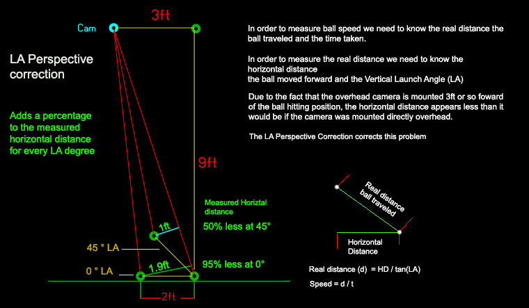
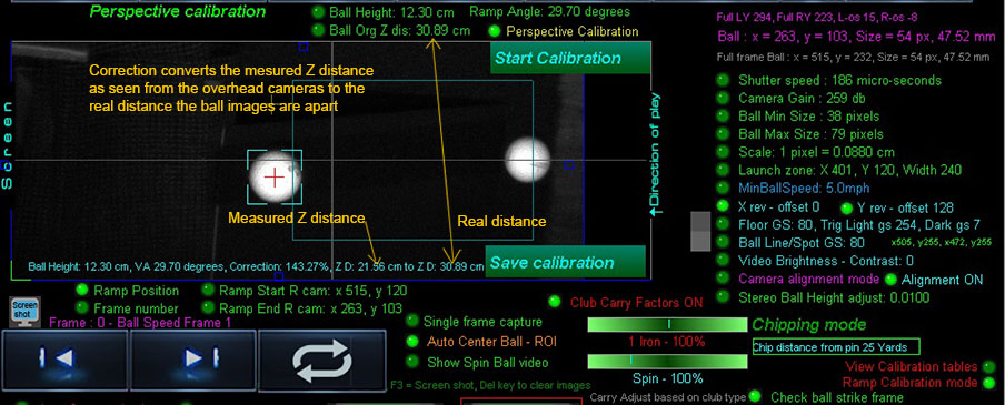
Z perspective correction calibration
The perspective calibration should be made for all VisTrak systems that feature a ceiling mounted camera
This method requires that balls be placed at various heights and readings be taken.
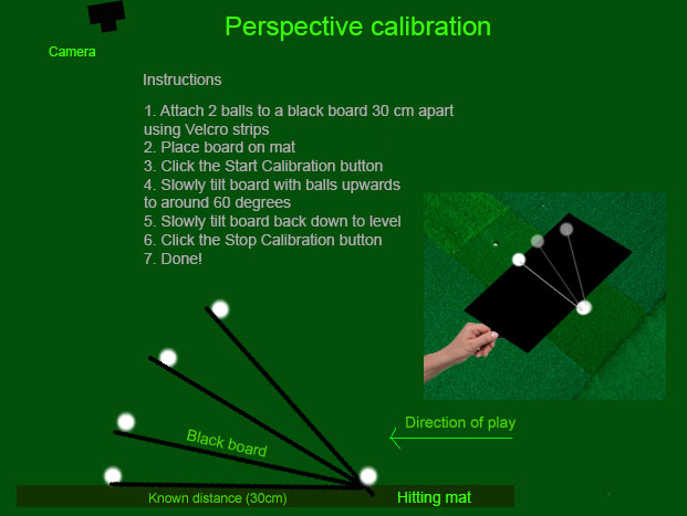
Instructions:
Step 1.
Place ball on mat in the usual hitting position and click the "Start/Stop VisTrak" button to set the base floor level.
Wait until you see the message " ball detected, waiting for swing"
Step 2.
Go to the camera panel and select camera 1.
Step 3.
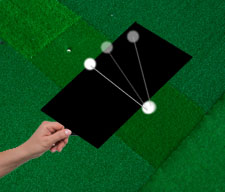
Using Velcro strips applied to the under side of 2 balls and on the board ,
attach the 2 balls to a (approx 12" x 18") black or dark card board, spaced at around 30 cm apart.
Foam board is ideal for this purpose
Step 4.
Click the "Soft Trigger" button to grab a new frame of the 2 balls.
This will set the measured distance the balls are apart
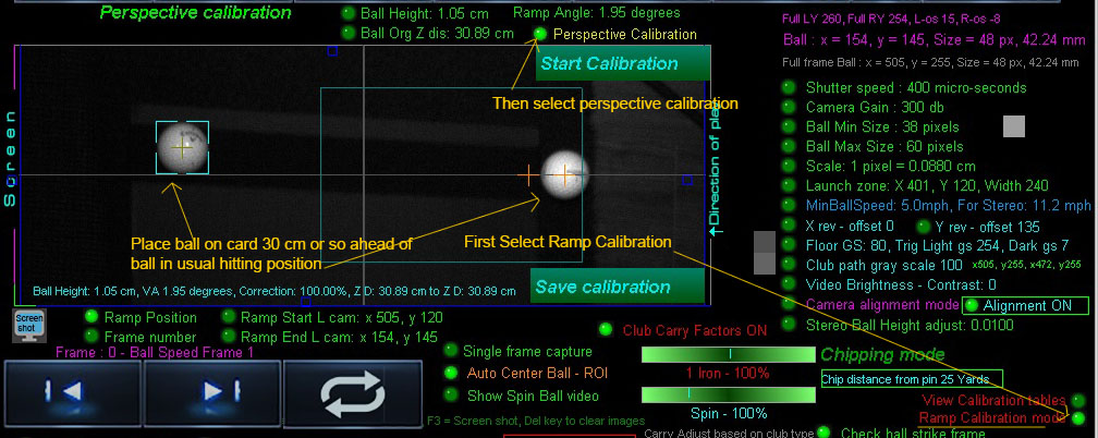
Step 5.
Click the "Start Calibration" button
The system will now start capturing images
Step 6.
Keeping your hand out of the FOV of the camera,
slowly tilt the board upwards to around 60 degrees and back again to level 0 degrees
The system will automatically measure the ball height, vertical launch angle and distance the
balls appear to be apart with each frame.
A comparison of the distance the balls appear to be apart with the new tilt angle
will be made to the distance the balls were measured apart with 0 degree tilt.
A correction value will then be calculated and entered into the perspective correction table.
Step 9.
Click the "Stop Calibration" button.
Optionally click the "Save Calibration" button.
Done!
![]()
Perspective correction table
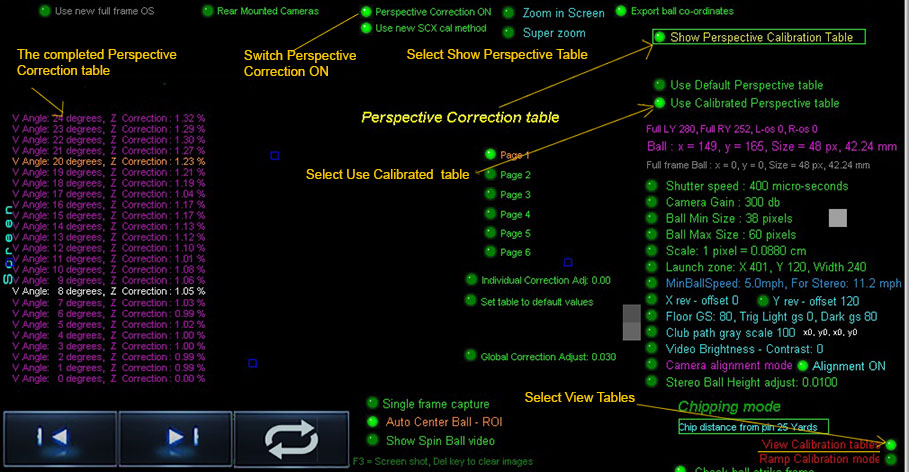
To view the Z Perspective Correction table,
1. click "View Calibration tables"
2. click "Show perspective Calibration tables"
To activate the table, switch " Perspectve Correction" ON
Select "Use Default Perspective table"
or
"Use Calibrated Perspective table"
Stereo camera Disparity explained
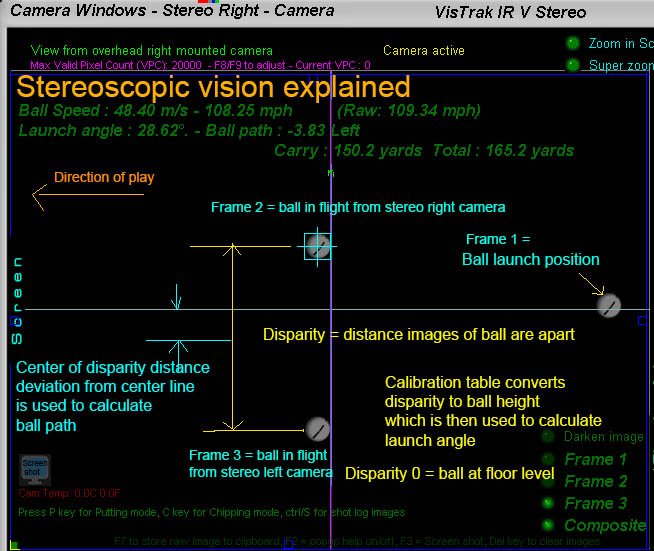
The above diagram explains the basic stereoscopic principles.
If the two 2 stereo cameras are aimed precisely at the center line and a ball is placed at floor level, the images of the will appear on top of each other.
The disparity of the ball is then zero (or near zero) and this is known as the "Converging point"
When the ball is elevated, the images of the ball in the camera frames will start to separate. The distance the ball images are apart is the "Disparity".
Using a "disparity to ball height" table, the exact height of the ball can be determined.
Knowing where the ball was before ball strike the ball LA and path can be determined.
Ball path is simply derived from the divergence the center of the disparity distance is from the center line.
i.e. a perfectly straight shot would show that the 2 ball images are the exact same distance from the center line.

![]()
![]()
 Home
Home Products
 Cameras
 Software
 Enclosures
 ProTee
 E6 Courses
 Business
 Tech News
 View Cart