![]()
Please note:
Regular stereo systems are now EOL (End of Life)
and are replaced with the new VisTrak system.
 -
-
Click above image to see the VisTrak systems
![]()

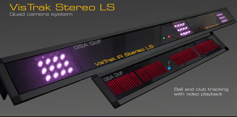
VisTrak IR Stereo LS Installation
![]()
Technical Support


Email and remote access support is available for all original purchasers of GSA Golf systems.
For all non original purchasers (i.e. purchasers of used GSA Golf systems) remote access support can be purchased separately.
Click above images for more information.
![]()
VisTrak IR installation overview
![]()
1. Unpacking the boxes
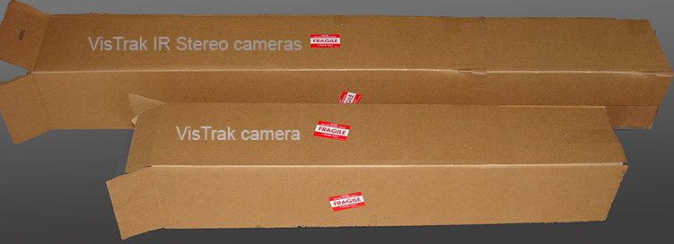
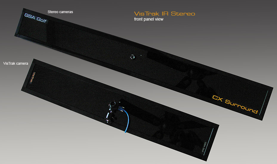
The VisTrak IR Stereo consists of two IR LED panel units with built in power supplies
1. The stereo camera panel (60" X 8")
with 2 separate USB Cat converters and Cat 5 cables plus projector mount hardware
2. The VisTrak camera panel (42" X 8")
with USB3 cables (30ft) plus projector mount hardware
The Lens is packaged separately and has to be screwed into the VisTrak camera after unpacking.
 --
--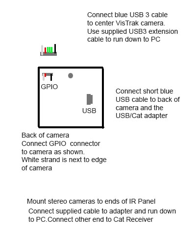
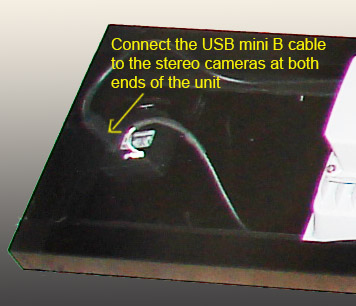
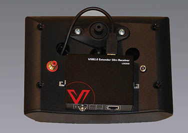
On the stereo unit, connect the GPIO and USB cables as shown above
![]()
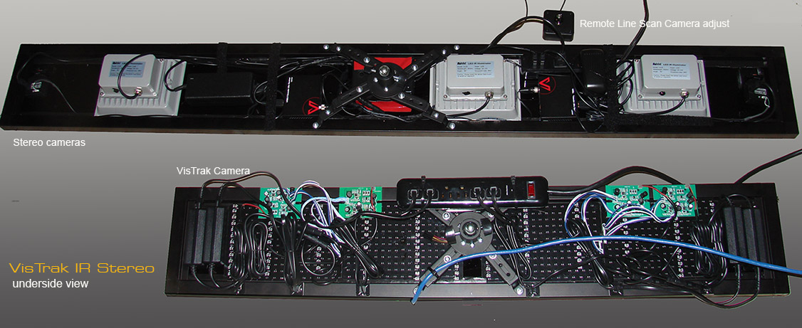
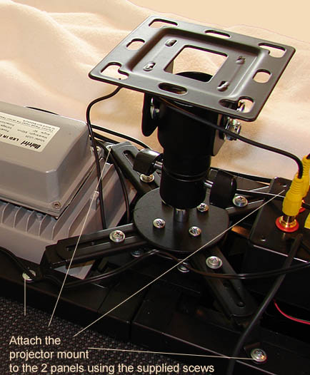
2. Mounting and wiring the 2 camera panels
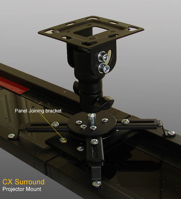

Both units feature projector mounts
The end piece is packaged separately and has to be mounted to the ball joint on the mount frame using the two wing screws.
Before doing this though, we recommend first mounting the projector end piece to the ceiling where the units are to be mounted.
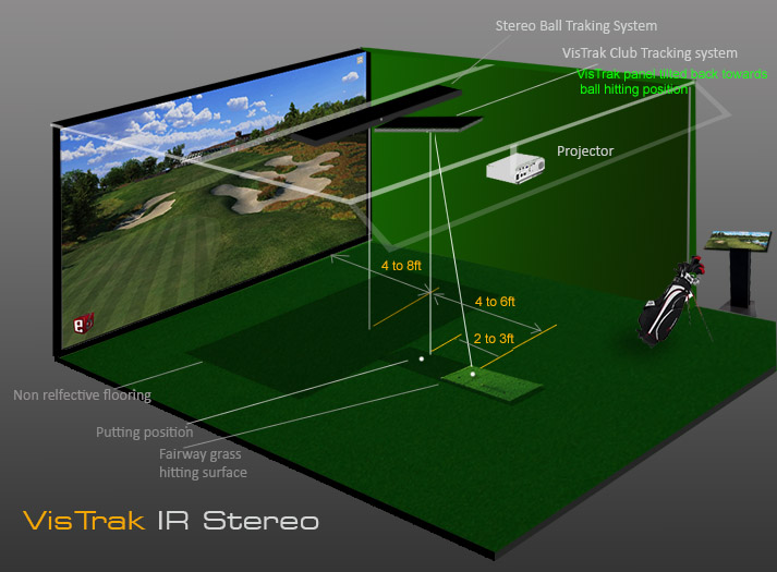
The above image shows where the two panels should be mounted
Non reflective flooring
Note that non-relective flooring is required for the stereo cameras to function
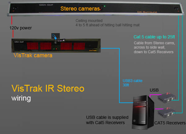
Stereo camera wiring
 -
-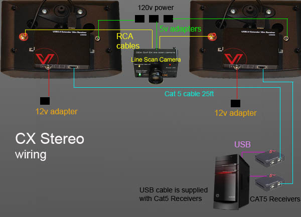
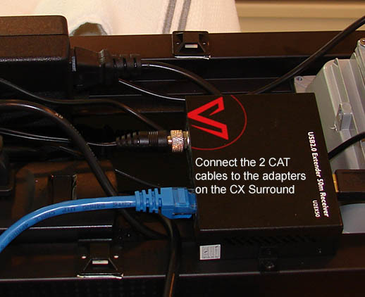
The stereo CX Surround cameras feature two USB to Cat cable converters.
Connect the 2 supplied CAT5 cables to the CAT adapter Receivers
and run the CAT cables down to the PC.
Connect the other ends of the CAT 5 cables to the CAT adapter transmitters
and connect the adapter to the PC ports using the supplied USB CAT adapter cables.
Which USB ports on the PC do I use?
Connect one of the Transmitters to a USB 2 or 3 port on the front of the PC and the other to a USB 2 port on the back of the PC
Always connect the VisTrak camera to a USB 3 port
Important ! USB 3 only for the VisTrak camera

The VisTrak camera is a USB 3 camera and must be connected to a USB 3 port on your PC.
You can identify a USB 3 port by the SS symbol next to the port
The VisTrak hi-speed camera will require a PC that is capable of running hi-speed cameras.
While most good desktop gaming PCs featuring i5 or i7 CPUs can do this, laptops are not suitable.
![]()
3. Installing the system software
Go to the "Installing the software" section on the VisTrak Installation page for software installation instructions and download links

Installing the game software
ProX Driving Range
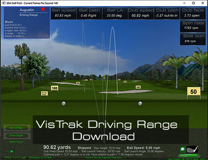
Download your free ProX Driving Range by clicking on the above image.
![]()
GSA Golf Game software download
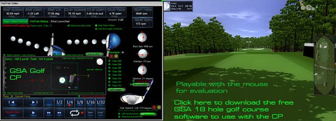
Note: If you encounter a windows error message stating that it could not find d3dx9_30.dll when starting GSA Golf,
download and copy the d3dx9_30.dll to your windows\SysWOW64 folder.
Download here d3dx9_30.dll
![]()
E6 Connect download

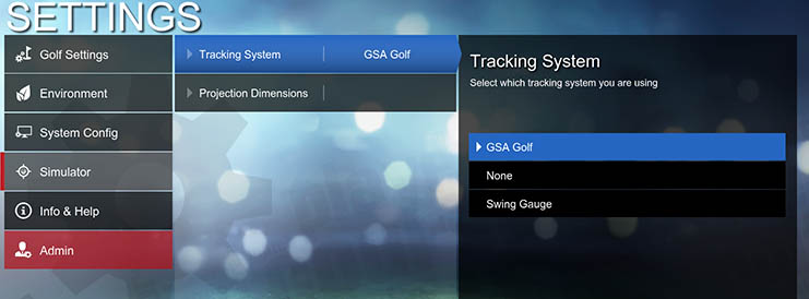
Select GSA Golf in the Settings / Simulator options
 -
-
Select E6 CONNECT in the GSA Golf Control Panel's main window
![]()
4. Checking and testing the cameras
Checking that the PC detects the cameras
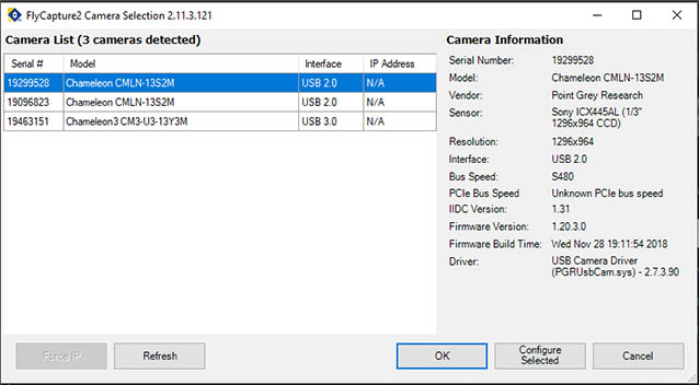
You can use the FLIR FlyCapture2 app to check that all the cameras are detected by the PC
The app is located in the
C:\Program Files (x86)\Point Grey Research\FlyCap2 Viewer\bin folder
and is called Point Grey FlyCap2
You should see that the PC detects 3 cameras as shown above. i.e. one USB3 camera and two USB 2 cameras.

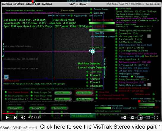
VisTrak Stereo Control Panel (CP) instructions.
All the cameras are controlled by the GSA Golf Control Panel
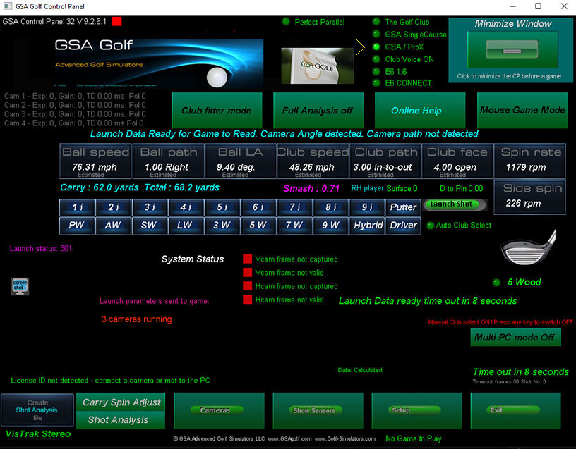
When you start the Control Panel and the cameras are connected to the PC, you should see the message "3 cameras running" on the main screen.
CX Surround and Stereo setup instructions
If you have a CX Surround or Stereo system without a VisTrak camera
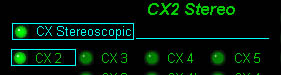
select CX2 and CX Stereoscopic in the CP's setup window .
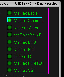
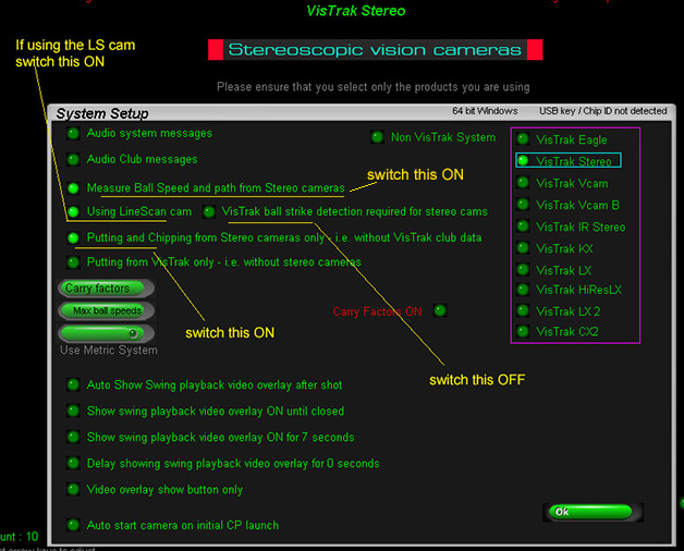
System Setup
Select VisTrak Stereo in this case
Select "VisTrak Stereo" in the CP's setup window if you have a VisTrak Stereo or VisTrak IR stereo system.
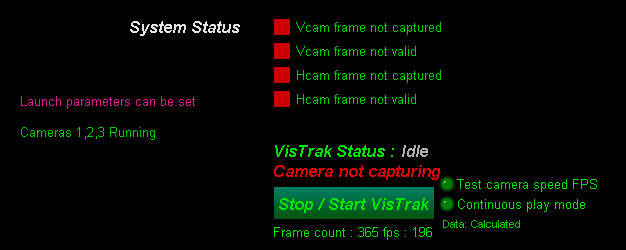
When all 3 cameras (VisTrak camera plus H and V cam cameras) are connected to the PC
ensure that you see the "Cameras 1,2,3 Running" message displayed in the CP's main panel.
Camera assignments
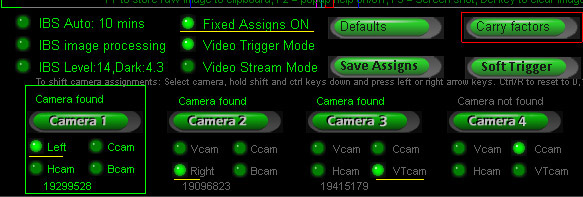
In the cameras panel, you should see the left camera as camera 1,
the right camera as camera 2,
and the VisTrak camera (VT cam) as camera 3.
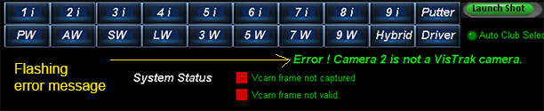
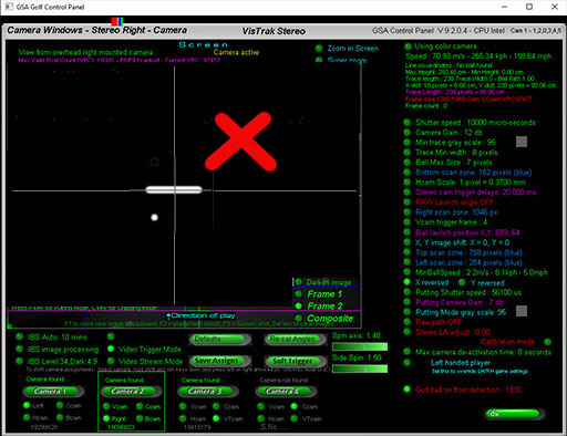
If you see this error message flashing when first starting the CP,
then the camera assignments are incorrect.
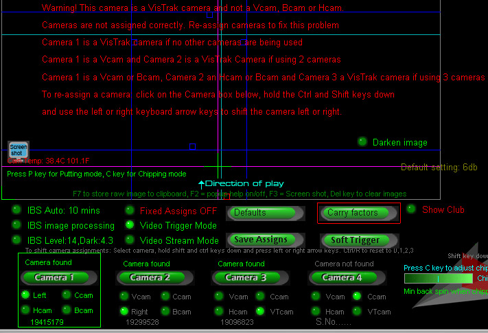
If you see a warning message like the above, the cameras have to be re-assigned as described in the error message.
Note: when re-assigning cameras, ensure that the "Fixed Assigns" option is OFF.
When the assingments are correct, switch the "Fixed Assigns" option back ON.

Follow the above instructions to re-assign the cameras to their correct positions.
Auto camera assignments

This new feature eliminates the need to manually assign the cameras.
Simply switch on the Auto Camera Assigns option and restart the CP.
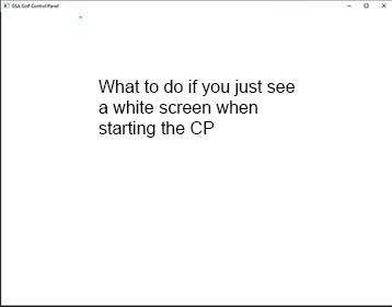
If the camera assignments aren't correct, then the CP may hang and just show a white screen when started.
To fix:
1. unplug all cameras from the PC.
2. restart the CP and switch the "Fixed Assigns" option OFF.
3. shut the CP down.
4. plug the cameras back into the PC and restart the CP.
5. Check that assignments are correct.
If it's a 2 camera system, then camera 1 is the Vcam camera and 2 is the VisTrak camera.
If it's a 3 camera system, then camera 1 is the Vcam camera, camera 2 the Hcam camera and 3 is the VisTrak camera.
If re-assigning cameras then the "Fixed Assigns" should be switched back ON again and the CP re-started
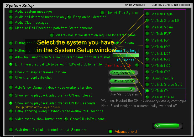
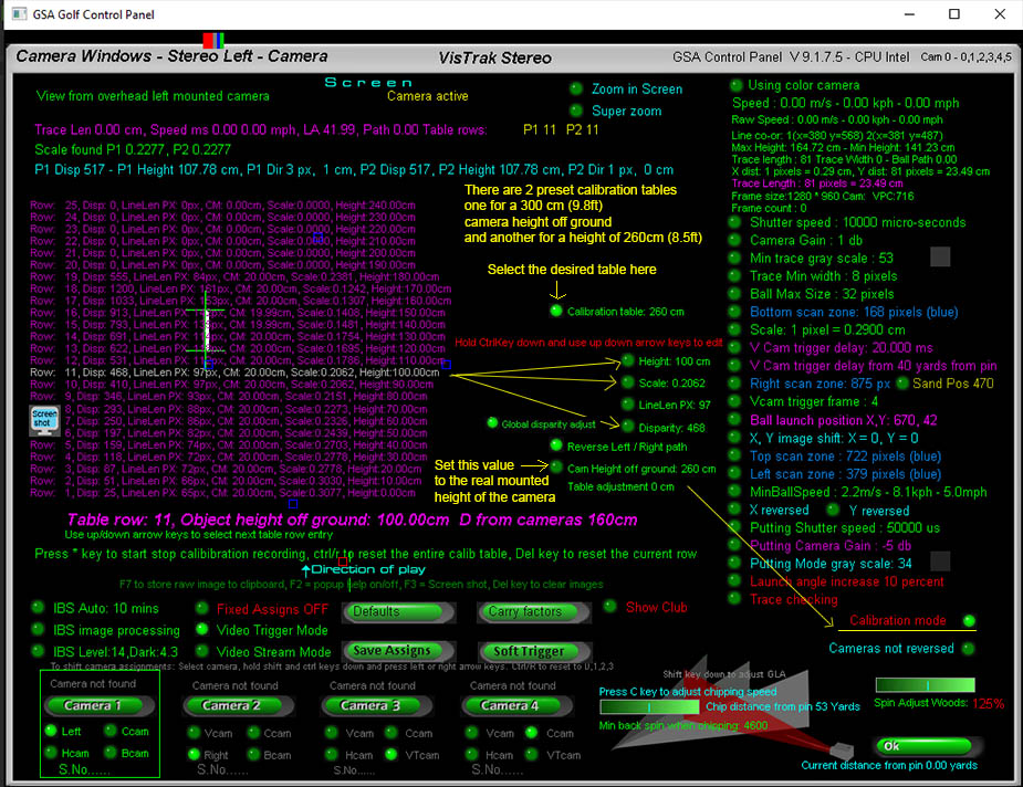
Standard setup settings
![]()
5. Checking and testing the VisTrak camera
Go to the VisTrak Installtion page to see how to install and check the VisTrak Camera
![]()
6. Checking and testing the line scan camera
SX Line scan camera
Note: This section is only for VisTrak Stereo LS systems
The regular VisTrak Stereo does not use a Line Scan camera
The CX Surround features a built-in Line Scan camera that is used to trigger the stereo cameras as the ball passes through its FOV.
The VisTrak Stereo system also includes an optional separate Line Scan camera.
The following Line Scan camera instructions apply to both the CX Surround, VisTrak Surround and the VisTrak Stereo.
With the VisTrak Stereo system, the SX Line Scan camera is mounted inbetween the two stereo cameras,
facing down with the marking "Screen" on the camera indicating in which direction the camera is mounted.
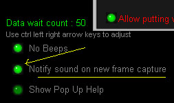
Line scan camera sensitivity
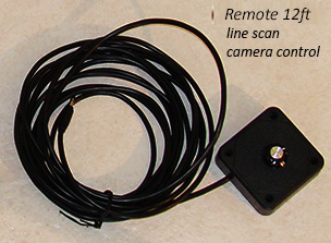
The Line Scan camera features a remote sensitivity control.
The sensitivity of the Line Scan camera has to be set so that both rolling balls on the floor as well as flying balls that pass under it
are detected and a trigger signal is sent to the stereo cameras.
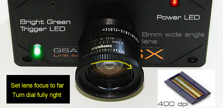
A bright green LED light on the Line Scan camera will turn ON for a few seconds when it detects a ball passing under it.
The SX line scan camera's sensitivity control is attached to the SX with a 12ft long cable.
Run the cable from the SX cam along the ceiling and a quarter-way down one of the side walls for easy access.
When adjusting the SX cam's sensitivity, it is important that you not stand under or too near the camera
as then your body will reflect light back into the camera.
Please note that the sensitivity control for the SX line scan camera is a 10 turn potentiometer !
i.e. you have to turn the dial 10 turns from one end to the other end.
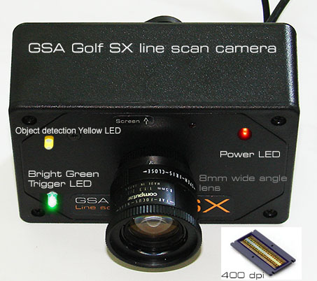
Note that the bright green trigger light does not always stay on when a ball or object is in the camera's FOV.
The green LED light usually just stays on for about 2 seconds and then automatically switches off
no matter if a ball or object is under the camera or not.
The green LED trigger light is powered by the camera trigger signal and in order for it to re-trigger
the object (e.g. a ball or person) has to first go out of the FOV and back in again.
Line scan camera setup problem solving
 6. Ensure that the mounting height of the LS camera is not greater than 9 ft
Use mount extensions to reduce the height of the line scan camera if your ceiling height is higher
![]()
7. Stereo Camera Trigger delays
Note: This section is only for VisTrak Stereo systems not using a Line Scan trigger camera
In order that the stereo cameras see the ball ahead of the ball striking position on the mat when not using a line scan trigger camera,
a camera trigger delay has to be set.
There are two methods of doing this:
1. Set a fixed trigger delay in the stereo cameras themselves
2. Set a variable ball speed depedant trigger delay from the VisTrak camera
Stereo camera fixed trigger delays
In the stereo camera windows of the CP, set the trigger delay for both cameras
Variable Ball speed Dependant trigger delays
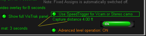
Switch on the SpeedTrigger for Variable Trigger delays from the Setup window.
Adjust the "Capture Distance" with the up/down arrow keys when the mouse is over the "Use SpeedTrigger" button.
The capture distance is where the Vcam or Stereo cameras will be triggered from the ball strike position so that the captured ball images
- no matter what speed they are traveling - will always be close to this distance.
8. Final Ball play checks
8. VisTrak / Stereo camera System Testing
We recommend testing the Stereo cameras and the VisTrak camera separately to start with.
i.e. First connect just the VisTrak camera to the PC and select "VisTrak Eagle" in the CP's Setup panel.
Confirm that the VisTrak camera functions correctly and is detecting all shots so that you are able to play a round of golf with it.
Then connect just the Stereo cameras (without the VisTrak camera) to the PC and select "CX2 Stereo" in the Setup panel of the CP.
Likewise, confirm that the Stereo cameras are functioning correctly and are detecting all shots so that you are able to play a round of golf with it.
![]()
The above section to be continued...
![]()
GSA Golf system minimum PC requirements

Intel i5 or above Processor
8GB RAM Nvidia 1070 Graphics Card or equivalent
(Dedicated GPU with DirectX 11 Support)
25GB of Hard Drive Space
Windows 10 (Required)
Internet Connection (Required)
When using VisTrak systems - Native USB3 ports (Required)
( i.e. no add-on PCie USB3 adapters for PCs that don't come with USB 3 ports as standard )
![]()
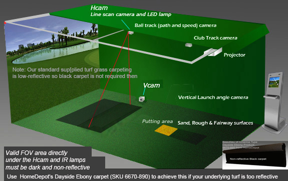
Non reflective flooring
Note that non-relective flooring is required for the stereo cameras to function
The above image shows a ball trace being well detected from the stereo cameras with the use of non-reflective flooring.
It is essential that the flooring is non-reflective!
And that there are no reflective objects in the valid field view of the cameras.
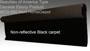
A recommended carpet is : Beaullieu of America - Type: Dayside Ebony, Product 6670-890 which is available at your local Home Depot store at around $4.00 a ft 6ft wide.
This carpet is also very good for lining the inside of your enclosure. Especially for the wall opposite the vertical camera.
You do not have to carpet the complete enclosure: only the part in the valid field of view of the camera.
![]()
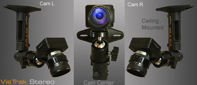
VisTrak Stereo separate camera mounting
CX Surround / CX Stereo cameras
The CX Surround and CX Stereo systems use two USB 2.0 cameras plus a line scan trigger camera
CX Surround / CX Stereo cameras with VisTrak
When used with the VisTrak camera, three cameras are used: Two USB 2.0 cameras and one USB 3.0 camera.
Stereo camera wiring
-
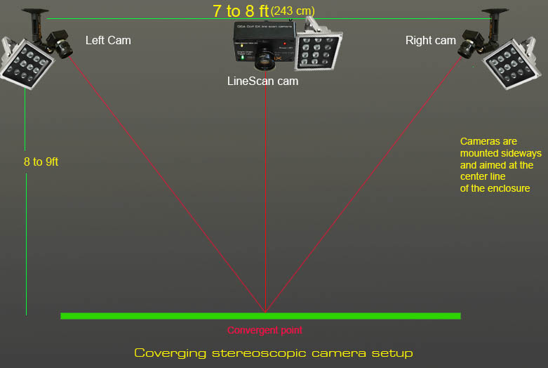
Individual stereo camera mounting
The two cameras ( V and H cams) are mounted around 4 to 6 ft ahead of the player's normal ball striking position and aproximately 7 to 8ft apart - centered.
Note that the cameras are mounted sideways in order to increase the left and right FOV.
Aiming the cameras to the center line
Place a white strip and a ball to one side close to the far end (the end nearest the screen) on the center line of the floor between the two cameras.
Starting with camera 1, select video stream mode and aim the camera so that the white strip appears as close as possible to the center of the image.
There are vertical and horizontal center lines visible in the image to help with this.
Do the same for camera 2.
Camera orientation

The two cameras should have the same orientation and show the same - just from a different angle
i.e. if you place a ball next to a white paper slip
and the left camera shows the ball to the left side of the white strip, then the right camera should show the ball to the left side of the strip too.
If one camera show the ball to the right, then use the "X reversed" option in one of the cameras to flip the image horizontally.
Also note that the direction of the play is always from bottom to top of the frame.
Thus ensure that the ball appears at the top of the line in the frames.
If not, then you can use the "Y Reversed" option to flip the image vertically or simply rotate the camera on its mount 180 degrees.
If one camera (or both cameras) show the white strip pointing horizontally, then the camera has to be rotated 90 degrees on its mount.
This is because pixel chip in the camera is rectangular and not square so the image cannot be rotated
![]()
VisTrak IR Stereo mounting
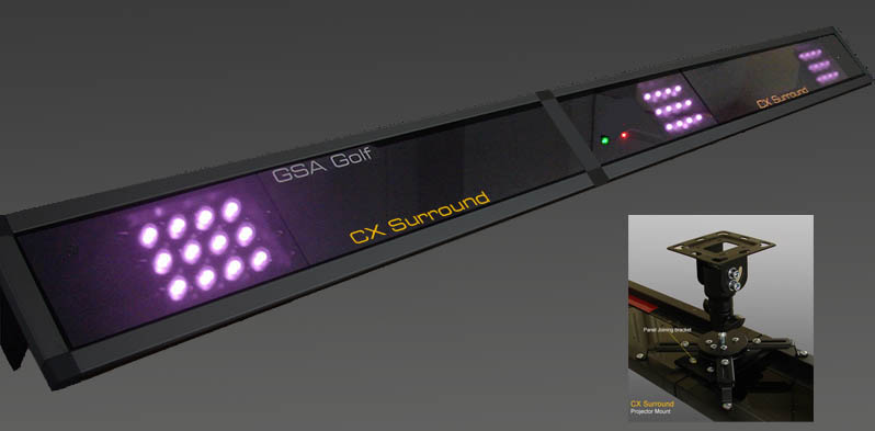
The new CX Surround case is shipped in 2 x 48" long panels to make the full width of 86" (7ft 2").
BTW: Foresights Sports GC Hawk is around 7.6ft in width so we're about the same here.
CX Surround assembly
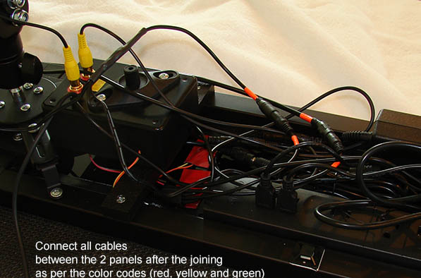
There are a few cables that have to be connected between the two panels.
All connections are color coded
![]()
![]()

VisTrak problem solving.
Click the below button to find solutions to common VisTrak user issues

![]()
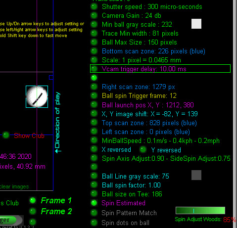
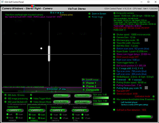
Setting up the Control Panel for Stereo Cameras
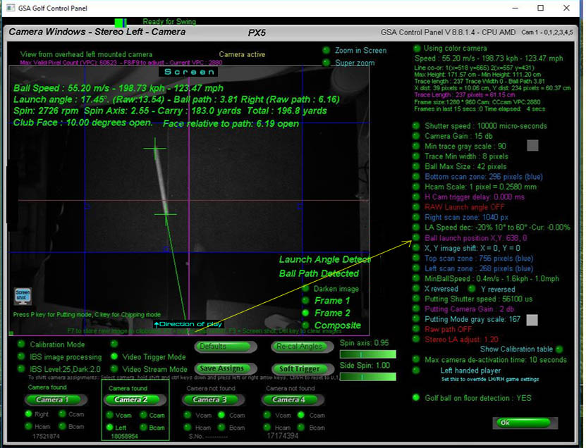
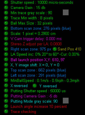
The Control Panel settings in both the left and right cameras should be similar to the above settings
Note that the ball launch position has to be set in both cameras too.
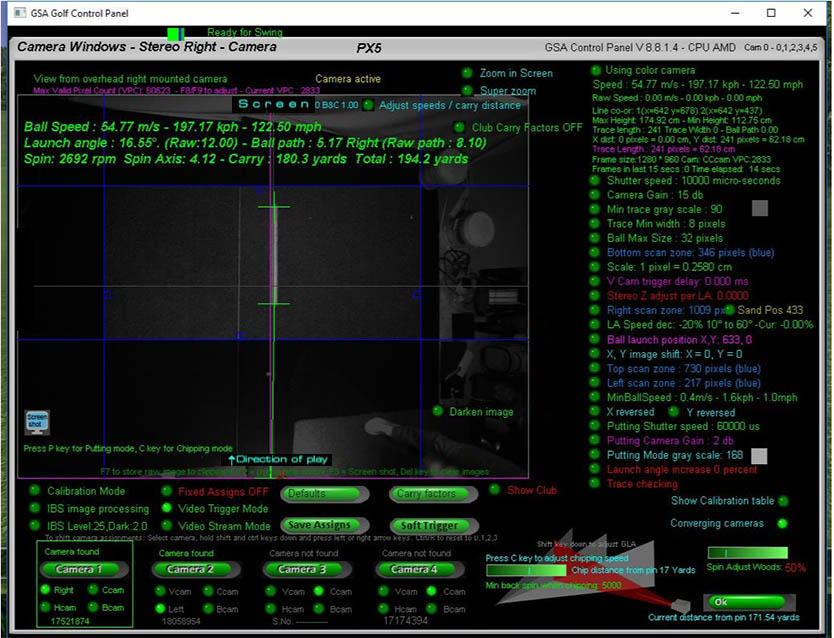
The above screen shots are from customer Kevin showing the left and right camera images of a full shot using the stereo setup.
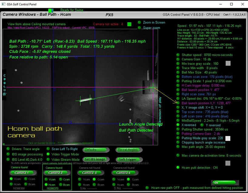
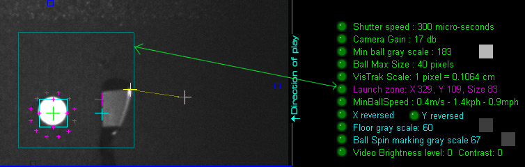
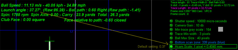
Ball traces
The image shows a ball trace from a shot from one of the two stereo cameras.
Note that there are two green cross hairs at either end of the ball trace and that the background within the blue scan zone border lines appears dark.
It is essential that the underlying floor surface be a dark and non-reflecting surface (carpet or turf)
so that there is sufficient contrast between ball trace and the surface.
If the turf carpet is too bright or reflective, then the IR Light pointing down on it will reflect back into the camera
and there won't be sufficient contrast for the ball trace to be detected.
If your carpet appears bright with a camera gain of 15db and a shutter speed of 10,000 micro-seconds
then you will have to replace or cover up the scan zone area under the cameras with a non-reflective carpet like the above carpet from Home-Depot.
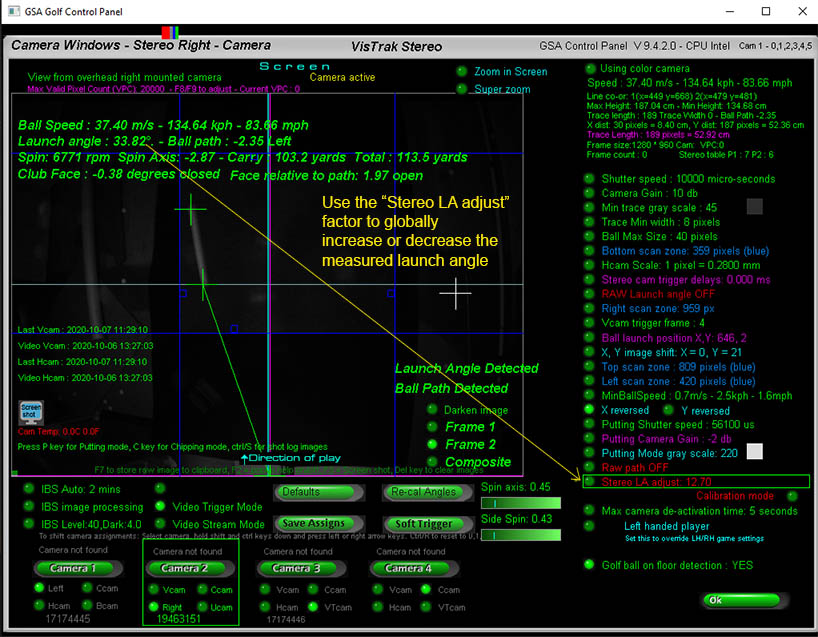
Stereo Vertical Launch Angle
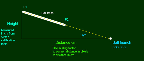
Two factors are required to measure the vertical launch angle of the ball: Distance and Height.
Distance
The user defined launch position of the ball and the end of the ball trace (P1) are used to determine the distance.
This distance is initially measured in pixels and thus has to be converted into a real world distance using the "Scaling factor".
Adjusting the scaling factor will thus directly effect the Vertical Launch angle calculation.
Height
The height of the ball is determined by the height values for a certain stereo disparity value of Point 1 of the ball trace in the Stereo Calibration table.
Ball Speed and Path
Two factors are required in order the measure ball speed: Distance and time.
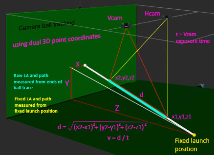
The Length of the ball trace determines the distance the ball has traveled and the camera exposure shutter speed is the time.
The stereo calibration table includes the scaling factors for all trace point disparities.
With these two factors we use the formula : speed = distance / time.
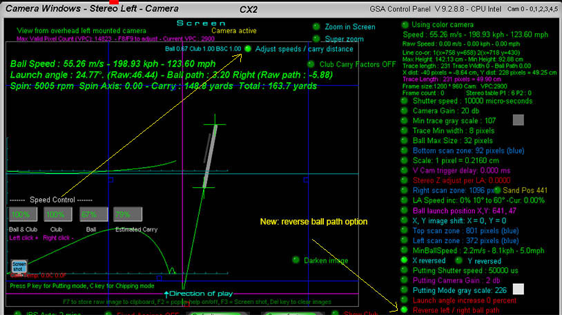
Ball speed can be adjusted with the speed controls (switch Adjust speeds /carry distances on in the Vcam window)
Ball path can now be reversed from this panel too.
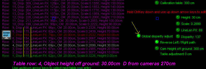
Editing the stereo calibration table
Adjusting the calibration table to suit the mounted camera height
The following example shows how to adjust the stereo calibration table to line up with the mounted camera height.
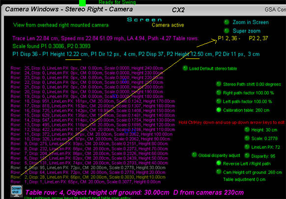
The above example image shows that Point 1 and 2 of the ball trace of a ball at floor level has a disparity of around 36.
The calibration table, however, has height entry levels of 10 to 20 cm off the ground for this disparity range.
The system thus calculates a ball height of 12.5 cm and not 0 cm.
To adjust the calibration table so that the disparity level of 36 corresponds to a ball height of 0 cm,
simply select the "Global Disparity Adjust" and - using the keyboard ctrl/ up arrow key - increase the disparity levels of all entries until the Row 1 disparity entry is 36.
Ball height is then correctly calculated to be 0 cm off the ground and all other entries are adjusted to match.
The values again are:
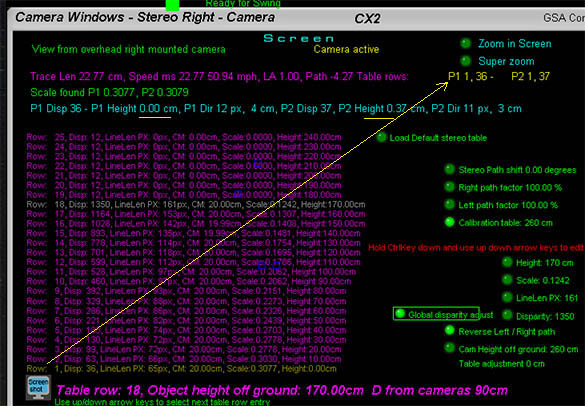
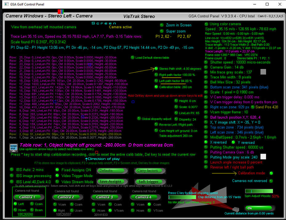
Why edit the table?
e.g. in the above image the disparity of a white card placed at a height of 100 cm is 517 for P1
(P1 is the upper end point of the ball trace. P2 is the lower end point of the ball trace.
These two points are shown by the two green cross hairs on either end of the ball trace)
In this example, the height for a disparity of 517 is calculated to be 107.78.
If, for example, the white card that represents the ball trace was placed at a height of 100 cm off the ground and not 107 cm,
then you would adjust the current disparity of 468 for a height of 100cm to 517.
The scaling factor - used to convert trace lengths measured in pixels to real distances in cm - can also be adjusted.
Using this method, you can verify and adjust values for the complete 19 row table.
Note that you have to place your white card at the desired height (0 to 190 cm) and hit the
Soft Trigger in both left and right cameras to grab new frames for every height you are checking.
There's now a global table disparity adjustment option. When ON, all disparity values are adjusted at one time using the up/down arrow keys while holding the ctrl key down.
The adjustments will effect the LA.
Adjusting ball path
You can adjust the measured ball path with the "Stereo Path Shift" factor and the R/L path factors without having to re-calibrate the cameras.
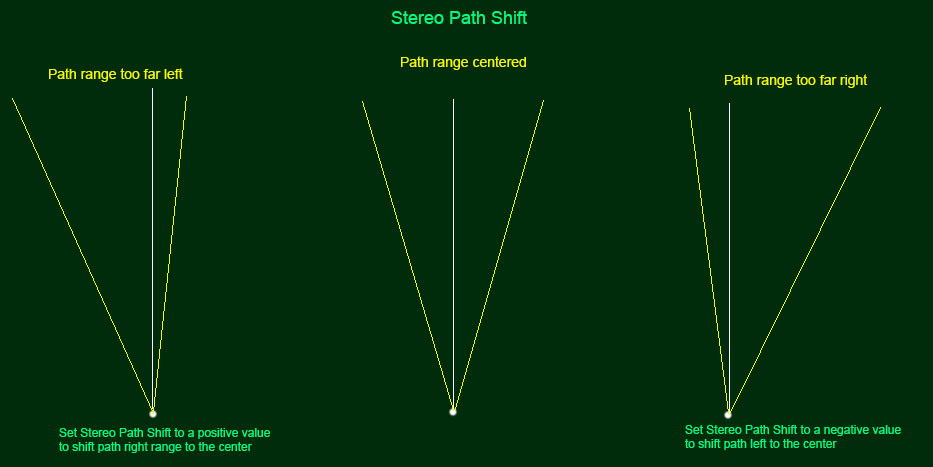
Use the Right / Left path factors to adjust measured ball path separately.
Adjusting stereo ball speed
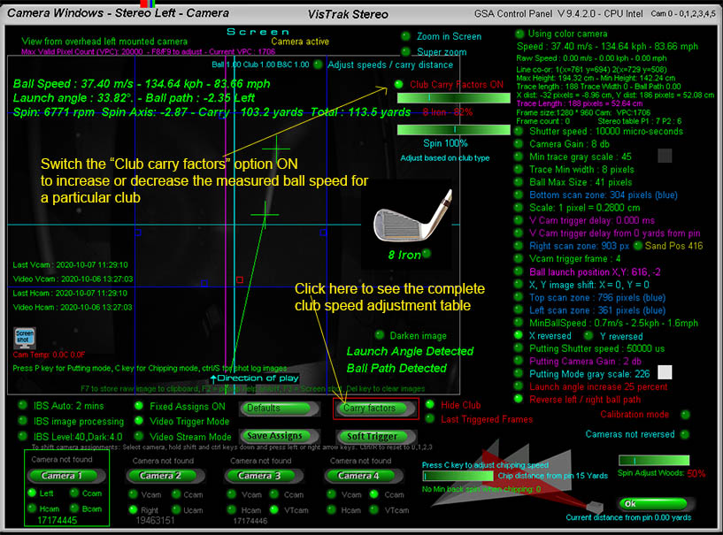
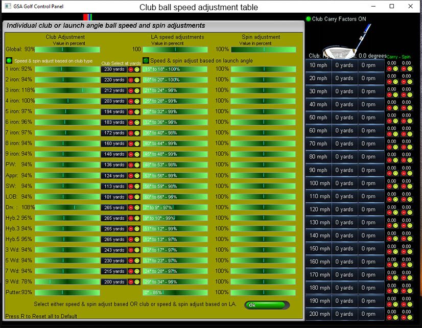
Open the "carry Factors" table to view all ball speed adjustments for a particular club.
Adjusting stereo ball launch angle
Hey Martin and Keith, I just wanted to say thanks and I am in love!!! I believe I have made almost all of my adjustments and the PX5 is awesome! Keith kept telling me to use IBS and I finally switched over tonight.... WOW! The images and reads are great. Attached is two 6 iron pics to show my IBS images. I played a full round tonight. No reads were at a minimum. I had one putt, one tee shot (which I launched from CP), but then I did have to close TGC and GSA and reopen when I was trying to take a half wedge shot that wasn't reading after multiple attempts. After the restart I believe I had one more no read. Keith- I started Q school tonight. My TGC username is Swiggs. It looks like you check on some of the scoring so I wanted to let you know I had one rewind near the very beginning. I hit my hybrid (on 5 wood setting) and it travelled 45 yards too far. I went into the CP and noticed spin was at 7000 and speed was 117%. I brought down to 100% and 3000ish spin and used the CP to relaunch after. ( I don't want to be the new guy who cheats and still gets last place! ha!)
Kevin
11/23/18
Hey Martin !
I have my cameras officially set up 13.5 feet apart and it is awesome! I did leave the IRs in the original spots about 3 feet apart. Launch angles are much more accurate. Only a small difference between LA and Raw LA. I used an online right angle calculator and the only thing I did was take it down 1* from what LA was reading.
I did have to slow my shutter speed to 7100. And I am now making small adjustments because every once in a while my wedge will enter the FOV again (which I had perfected in 5.5 foot setup.) So just a few small adjustments angling my line scan a hair further back and sliding the FOV a tiny bit.
My BIG breakthrough was with the PX mat! I decided since the shaft’s shadow was picking up and always reading wide open to put my ball just off center of tee holder and also angle my halogen light towards me. This way the shadow of the shaft never is able to be sensed no matter how much shaft lean.
So my report is I am loving it!!! Feels even more accurate. Club readings, ball readings, putting have all been awesome as of my initial few hours with the new setup.
Kevin
01/28/19
Pros and Cons of Stereoscopic vs H cam V cam setups
 Home
Home Sensors
 Cameras
 Software
 Enclosures
 GSA Courses
 E6 Courses
 Business
 Tech News