


SCX AI
SCX AI is a free software update for all GSA Golf launch monitor models

New AI Ball Spin
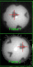
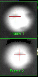
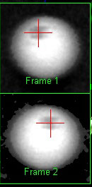

As of CP version 10.4.9.8
The new AI methods of detecting back and side spin are being used.
As such, no specific adjustments have to be made
Even with ridiculously out of focus and big motion blur images of the ball in flight,
the method can still detect the markings on the balls and detect spin.
For some time now (over a year) I've been experimenting and testing AI methods and AI generated code of camera image ball and club tracking.
I'm at a point now where I can start integrating these methods and code into the current CP software.
Once completed, this will vastly improve the accuracy of the SCX tracking - in particular - ball back and side spin detection
and make the SCX equally as good as any other launch monitor on the market today that is in the $10,000 plus range
while still keeping the SCX super low starting price of just $1,699.
As most probably already know, AI is making leaps and bounds in development with Artificial General Intelligence (AGI) only a few months away
and Superintelligence (ASI) only a couple of years away.
Even in its current state of development, AI can solve most problems it is presented with,
while AGI matches or surpasses human cognitive capabilities across virtually all domains.
And ASI is estimated to be more than a thousand times more intelligent than the combined intelligence of all human intelligence that ever existed.
It has been stated by most AI companies that ASI will be able to solve any problem presented to it.
Including: Curing all known diseases including Cancer and stopping the aging process so that we live forever.
Of course, when in the wrong hands, rogue AI can equally totally disrupt and destroy our world as we know it.
e.g. totally disrupting the internet, taking over the SWIFT banking system so that bank accounts are depleted,
shutting down major infrastructures causing major power blackouts, developing thousands of Viruses far more dangerous than Covid
and unleashing them on human society etc,etc...
In contrast to HAL ( the rogue super computer in the ScFi film 2001: A Space Odyssey) where the crew could simply pull the plug on its main brain functions,
rogue AI can self replicate itself thousands of times on thousands of servers around the world. i.e. you can't stop it.
One can only hope this doesn't happen in our lives but I fear it will sooner or later.
Anyway, bearing all this super intelligence in mind, I have no doubt that when presented with a super simple task such as to precisely measure
a golf ball's spin from a camera is absolutely peanuts.

Main Objectives
1. Increase accuracy of ball back and side spin
2. Detect club face angle, path and speed without the requirement to use markings on the club
3. Increase ball speed, VLA and HLA accuracy
Please note that whether or not the adaption of these AI generated functions and methods
actually result in significant advantages to the current methods used in the GSA Golf launch monitors
remains to be seen.
Comparison tests will be conducted over the next few months and results will be published as soon as they come in.
Coding examples
Image matching
1. Increase accuracy of ball back and side spin
2. Detect club face angle, path and speed without the requirement to use markings on the club
Both these tasks require image matching
The current "Template" matching method will be replaced by the new "Feature" matching method
AI generated code example for "Feature" matching :
AI says:
"If the sub-image has been distorted, tilted, or scaled down, template matching will fail.
Instead, you can use SIFT (Scale-Invariant Feature Transform) to find unique mathematical anchor points in both images and pair them up."
if (img_template.empty() || img_main.empty()) {
std::cout << "Error loading images." << std::endl;
return -1;
}
// 2. Detect keypoints and calculate descriptors using SIFT
cv::Ptr<cv::SIFT> detector = cv::SIFT::create();
std::vector<cv::KeyPoint> keypoints_template, keypoints_main;
cv::Mat descriptors_template, descriptors_main;
detector->detectAndCompute(img_template, cv::noArray(), keypoints_template, descriptors_template);
detector->detectAndCompute(img_main, cv::noArray(), keypoints_main, descriptors_main);
// 3. Match descriptor vectors using a FLANN-based matcher
cv::Ptr<cv::DescriptorMatcher> matcher = cv::DescriptorMatcher::create(cv::DescriptorMatcher::FLANNBASED);
std::vector<std::vector<cv::DMatch>> knn_matches;
matcher->knnMatch(descriptors_template, descriptors_main, knn_matches, 2);
// 4. Filter matches using Lowe's ratio test
std::vector<cv::DMatch> good_matches;
for (size_t i = 0; i < knn_matches.size(); i++) {
if (knn_matches[i][0].distance < 0.7 * knn_matches[i][1].distance) {
good_matches.append(knn_matches[i][0]);
}
}
// 5. Draw and save the matching lines
cv::Mat img_matches;
cv::drawMatches(img_template, keypoints_template, img_main, keypoints_main,
good_matches, img_matches, cv::Scalar::all(-1), cv::Scalar::all(-1),
std::vector<char>(), cv::DrawMatchesFlags::NOT_DRAW_SINGLE_POINTS);
cv::imwrite("feature_matches_cpp.jpg", img_matches);
std::cout << "Found " << good_matches.size() << " good feature matches." << std::endl;
return 0;
}
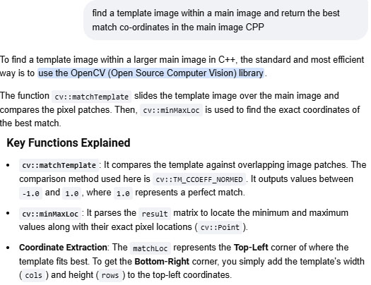
#include <opencv2/opencv.h>
#include <iostream>
int main() {
// 1. Load the main image and the template image in grayscale
// (Grayscale is faster and usually sufficient for template matching)
cv::Mat mainImage = cv::imread("main_image.jpg", cv::IMREAD_GRAYSCALE);
cv::Mat templateImage = cv::imread("template_image.jpg", cv::IMREAD_GRAYSCALE);
// Check if images loaded successfully
if (mainImage.empty() || templateImage.empty()) {
std::cout << "Error: Could not load images!" << std::endl;
return -1;
}
// 2. Create a matrix to store the match comparison results
cv::Mat result;
// 3. Perform template matching
// TM_CCOEFF_NORMED is highly recommended as it normalizes values between 0 and 1
cv::matchTemplate(mainImage, templateImage, result, cv::TM_CCOEFF_NORMED);
// 4. Find the coordinates of the best match
double minVal;
double maxVal;
cv::Point minLoc;
cv::Point maxLoc;
cv::Point matchLoc;
cv::minMaxLoc(result, &minVal, &maxVal, &minLoc, &maxLoc, cv::Mat());
// For TM_CCOEFF_NORMED, the maximum value indicates the best match
matchLoc = maxLoc;
// 5. Output the results
std::cout << "Best match confidence: " << maxVal * 100 << "%" << std::endl;
std::cout << "Top-Left Coordinate: (" << matchLoc.x << ", " << matchLoc.y << ")" << std::endl;
std::cout << "Bottom-Right Coordinate: ("
<< matchLoc.x + templateImage.cols << ", "
<< matchLoc.y + templateImage.rows << ")" << std::endl;
return 0;
Mapping a dot on a 2D image of a ball to its true 3D position on the surface of the ball
Note: True dot mapping is required to determine the amount of both back and side spin rotation
AI says:
"To map a dot on a 2D image of a spherical ball to its true 3D position on the surface of that ball, you must correct for perspective distortion.
Because a ball is a 3D sphere, a dot near the edge of the image appears squished and closer to the center than it actually is.
To solve this, you need to calculate the dot's true 3D spherical coordinates (latitude and longitude) relative to the center of the ball."
Here is how to implement this calculation using OpenCV in C++.
This code takes the detected center of the ball, its radius, and the pixel coordinates of the dot, then outputs its true 3D surface vector.
AI generated code example for "Dot" mapping :
// Function to calculate true 3D surface position from 2D pixel coordinates
Point3D getTrue3DPosition(cv::Point2f ballCenter, double ballRadius, cv::Point2f dotPixel) {
// 1. Shift origin to the center of the ball
double x_rel = dotPixel.x - ballCenter.x;
double y_rel = ballCenter.y - dotPixel.y; // Invert Y because image pixels go down, Cartesian goes up
// 2. Calculate the 2D pixel distance from the center
double r = std::sqrt(x_rel * x_rel + y_rel * y_rel);
// Handle edge case: if the dot is mathematically outside the radius due to pixel blur
if (r > ballRadius) {
r = ballRadius;
}
// 3. Calculate the true Z depth (facing the camera)
double z_rel = std::sqrt((ballRadius * ballRadius) - (r * r));
// 4. Normalize the vector to get unit coordinates on the sphere's surface (-1.0 to 1.0)
Point3D truePos;
truePos.x = x_rel / ballRadius;
truePos.y = y_rel / ballRadius;
truePos.z = z_rel / ballRadius;
return truePos;
}
int main() {
// Example: A ball centered at (300, 300) with a 100-pixel radius
cv::Point2f center(300.0f, 300.0f);
double radius = 100.0;
// A dot detected at pixel (350, 250)
cv::Point2f dot(350.0f, 250.0f);
Point3D surfacePos = getTrue3DPosition(center, radius, dot);
std::cout << "True 3D Vector on Sphere Surface:\n";
std::cout << "X: " << surfacePos.x << " (Right)\n";
std::cout << "Y: " << surfacePos.y << " (Up)\n";
std::cout << "Z: " << surfacePos.z << " (Depth toward camera)\n";
// Convert to Latitude / Longitude angles if needed
double longitude = std::atan2(surfacePos.x, surfacePos.z) * 180.0 / CV_PI;
double latitude = std::asin(surfacePos.y) * 180.0 / CV_PI;
std::cout << "\nSpherical Coordinates:\nLon: " << longitude << "°, Lat: " << latitude << "°\n";
return 0;
}
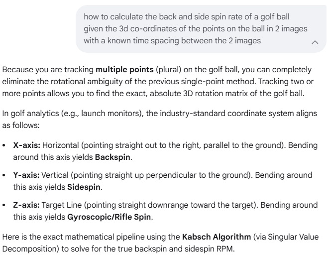
How to determine the amount of back and side spin rotation of a ball given 2 dots on 2 2D images of the ball
AI says:
If you track two distinct dots (A and B) across both images, you can build a unique 3D coordinate system (a "triad") for each image.
Multiplying these coordinate systems gives you the exact 3x3 rotation matrix, including any spinning.
AI generated code example for 3D rotation
// Expects normalized 3D positions for two dots (A and B) in both image states
cv::Mat getFull3DRotation(cv::Point3f A1, cv::Point3f B1, cv::Point3f A2, cv::Point3f B2) {
// Helper lambda to construct an orthogonal 3D coordinate frame matrix [X | Y | Z]
auto buildFrame = [](cv::Point3f A, cv::Point3f B) {
cv::Point3f x_axis = A; // Use dot A as the primary anchor
cv::Point3f z_axis = A.cross(B); // Perpendicular to both dots
z_axis = z_axis * (1.0 / cv::norm(z_axis));
cv::Point3f y_axis = z_axis.cross(x_axis); // Completes the right-handed frame
cv::Mat M = (cv::Mat_<double>(3, 3) <<
x_axis.x, y_axis.x, z_axis.x,
x_axis.y, y_axis.y, z_axis.y,
x_axis.z, y_axis.z, z_axis.z);
return M;
};
// 1. Build the 3D frame for Image 1 and Image 2
cv::Mat M1 = buildFrame(A1, B1);
cv::Mat M2 = buildFrame(A2, B2);
// 2. Compute the final rotation matrix: R = M2 * Matrix_Transpose(M1)
cv::Mat R = M2 * M1.t();
return R;
}
How to read the resulting Matrix R
Once you have the 3x3 rotation matrix R, you can extract the exact human-readable breakdown of the movement:
Total Angular Travel:\(\text{Total\ Angle}=\arccos \left(\frac{\text{Trace}(R)-1}{2}\right)\)(In OpenCV: double angle = acos((cv::trace(R)[0] - 1.0) / 2.0);)
Euler Angles (Pitch, Roll, Yaw): You can convert R directly into degrees of rotation relative to your camera's viewport axes.
To help write the code that extracts the specific angles you need, tell me:Are you looking for a single total angle of movement or the specific pitch/yaw/roll values?
If you have more than 2 dots (a cloud of dots), would you like to see how to use Singular Value Decomposition (SVD) to filter out measurement noise?
Example 2
How to determine the amount of back and side spin rotation of a ball given 2 dots on 2 2D images of the ball
AI says:
cpp
#include <iostream>
#include <cmath>
#include <Eigen/Dense>
// Structure to hold the calculated spins in Revolutions Per Minute (RPM)
struct GolfBallSpin {
double backspinRPM;
double sidespinRPM;
double riflespinRPM;
double totalSpinRPM;
};
/**
* Calculates the spin components of a golf ball.
*
* @param P1 3D points relative to the ball's center in Frame 1 (3 x N matrix)
* @param P2 3D points relative to the ball's center in Frame 2 (3 x N matrix)
* @param deltaTimeSec Time difference between Frame 1 and Frame 2 in seconds
* @return GolfBallSpin structure containing spin values in RPM
*/
GolfBallSpin calculateGolfBallSpin(const Eigen::Matrix3Xd& P1, const Eigen::Matrix3Xd& P2, double deltaTimeSec) {
// 1. Solve Orthogonal Procrustes problem to find the optimal rotation matrix R
// Matrix dimensions: P1 is (3 x N), P2 is (3 x N) -> H is (3 x 3)
Eigen::Matrix3d H = P1 * P2.transpose();
Eigen::JacobiSVD<Eigen::Matrix3d> svd(H, Eigen::ComputeFullU | Eigen::ComputeFullV);
Eigen::Matrix3d U = svd.matrixU();
Eigen::Matrix3d V = svd.matrixV();
Eigen::Matrix3d R = V * U.transpose();
// Handle potential reflection (det(R) == -1)
if (R.determinant() < 0) {
V.col(2) *= -1.0;
R = V * U.transpose();
}
// 2. Convert Rotation Matrix to Axis-Angle representation
Eigen::AngleAxisd angleAxis(R);
double angleRad = angleAxis.angle(); // Total rotation angle in radians
Eigen::Vector3d axis = angleAxis.axis(); // Unit vector of the rotation axis
// 3. Calculate Angular Velocity vector (radians per second)
Eigen::Vector3d angularVelocityRadSec = (angleRad / deltaTimeSec) * axis;
// Convert radians per second to RPM (1 rad/sec = 60 / (2 * pi) RPM)
const double radSecToRPM = 60.0 / (2.0 * M_PI);
Eigen::Vector3d angularVelocityRPM = angularVelocityRadSec * radSecToRPM;
// 4. Map to standard Launch Monitor Coordinate System:
// X = Right, Y = Forward (Target Line), Z = Up
GolfBallSpin spin;
// Backspin is typically modeled as rotation around the X-axis.
// In a right-handed system, a negative X-rotation rolls the top of the ball backward.
spin.backspinRPM = -angularVelocityRPM.x();
// Sidespin is rotation around the Z-axis (vertical axis).
spin.sidespinRPM = angularVelocityRPM.z();
// Rifle spin (axis of travel) is rotation around the Y-axis.
spin.riflespinRPM = angularVelocityRPM.y();
spin.totalSpinRPM = angularVelocityRPM.norm();
return spin;
}
int main() {
// Example Setup:
// High-speed camera frame rate = 10,000 FPS -> dt = 0.0001 seconds
double dt = 0.0001;
// Define 3 sample tracked surface features relative to the center of the ball
Eigen::Matrix3Xd frame1Points(3, 3);
frame1Points << 0.021, -0.010, 0.005, // Point 1 (X, Y, Z) in meters
0.000, 0.021, -0.015, // Point 2
0.011, 0.011, 0.018; // Point 3
// Simulate pure backspin (e.g., a 20-degree rotation around the negative X-axis)
double simAngle = -20.0 * M_PI / 180.0;
Eigen::Matrix3d simR;
simR = Eigen::AngleAxisd(simAngle, Eigen::Vector3d::UnitX());
Eigen::Matrix3Xd frame2Points = simR * frame1Points;
// Calculate Spin
GolfBallSpin result = calculateGolfBallSpin(frame1Points, frame2Points, dt);
// Display Results
std::cout << "--- Golf Ball Spin Estimation ---\n";
std::cout << "Backspin: " << result.backspinRPM << " RPM\n";
std::cout << "Sidespin: " << result.sidespinRPM << " RPM\n";
std::cout << "Riflespin: " << result.riflespinRPM << " RPM\n";
std::cout << "Total Spin: " << result.totalSpinRPM << " RPM\n";
return 0;
}
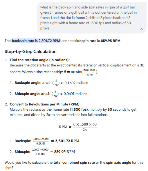
How to ask AI what the back and side spin rates are given the x,y shifts of a point on the ball between 2 frames
AI says:
cpp
#include <iostream>
#include <cmath>
#include <algorithm>
// Structure to hold 3D vector coordinates
struct Vector3D {
double x, y, z;
};
// Structure to hold the calculated spin values in RPM
struct GolfSpin {
double backspin; // Positive means backspin, negative means topspin
double sidespin; // Direction depends on camera placement (e.g., left/right)
double rifleSpin; // Gyroscopic spin around the camera's optical axis
double totalSpin; // Total magnitude of the spin
};
/**
* Calculates golf ball spin components in RPM from a tracked dot.
*
* @param x1, y1 Coordinates of the dot in Frame 1 (relative to ball center)
* @param x2, y2 Coordinates of the dot in Frame 2 (relative to ball center)
* @param radiusPlx Radius of the ball in pixels (e.g., 50.0)
* @param frameRate Camera frame rate in Hz (e.g., 1500.0)
* @return GolfSpin Calculated spin values in RPM
*/
GolfSpin calculateGolfSpin(double x1, double y1, double x2, double y2, double radiusPlx, double frameRate) {
GolfSpin spin = {0.0, 0.0, 0.0, 0.0};
// 1. Reconstruct Z coordinates on the sphere surface (assuming front hemisphere facing camera)
double z1_sq = radiusPlx * radiusPlx - x1 * x1 - y1 * y1;
double z2_sq = radiusPlx * radiusPlx - x2 * x2 - y2 * y2;
// Clamp to 0 to prevent negative values due to floating-point rounding errors near the edges
double z1 = std::sqrt(std::max(0.0, z1_sq));
double z2 = std::sqrt(std::max(0.0, z2_sq));
Vector3D v1 = {x1, y1, z1};
Vector3D v2 = {x2, y2, z2};
// 2. Calculate the cross product to find the perpendicular rotation axis
Vector3D cross = {
v1.y * v2.z - v1.z * v2.y,
v1.z * v2.x - v1.x * v2.z,
v1.x * v2.y - v1.y * v2.x
};
double crossNorm = std::sqrt(cross.x * cross.x + cross.y * cross.y + cross.z * cross.z);
// If the dot didn't move or moved perfectly linearly through the center (ambiguous), spin is 0
if (crossNorm < 1e-6) {
return spin;
}
// Normalize the axis of rotation
Vector3D axis = {cross.x / crossNorm, cross.y / crossNorm, cross.z / crossNorm};
// 3. Calculate the rotation angle (theta) using the dot product
double dot = v1.x * v2.x + v1.y * v2.y + v1.z * v2.z;
double cosTheta = dot / (radiusPlx * radiusPlx);
cosTheta = std::max(-1.0, std::min(1.0, cosTheta)); // Clamp to avoid NaN in acos
double theta = std::acos(cosTheta); // Radians
// 4. Convert angular velocity to RPM (Revolutions Per Minute)
// RPM = (theta / dt) * (60 / 2*pi)
double dt = 1.0 / frameRate;
double radPerSec = theta / dt;
spin.totalSpin = radPerSec * (60.0 / (2.0 * M_PI));
// 5. Map rotation axis components to golf spin conventions
// - Rotation around X-axis creates vertical movement (Backspin/Topspin)
// - Rotation around Y-axis creates horizontal movement (Sidespin)
// - Rotation around Z-axis creates rifle/gyro spin
// Sign convention adjustment: Right-hand rule means a negative X axis rotation
// corresponds to the front face moving upward (true golf backspin)
spin.backspin = -axis.x * spin.totalSpin;
spin.sidespin = axis.y * spin.totalSpin;
spin.rifleSpin = axis.z * spin.totalSpin;
return spin;
}
int main() {
// Example usage:
// Dot shifts slightly right (+x) and up (+y) between frames
double x1 = 5.0, y1 = 10.0;
double x2 = 7.0, y2 = 12.0;
double radius = 50.0;
double fps = 1500.0;
GolfSpin result = calculateGolfSpin(x1, y1, x2, y2, radius, fps);
std::cout << "--- Golf Ball Spin Results ---" << std::endl;
std::cout << "Total Spin: " << result.totalSpin << " RPM" << std::endl;
std::cout << "Backspin: " << result.backspin << " RPM" << std::endl;
std::cout << "Sidespin: " << result.sidespin << " RPM" << std::endl;
std::cout << "Rifle Spin: " << result.rifleSpin << " RPM" << std::endl;
return 0;
}
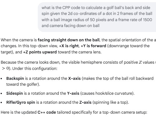
How to calculate the back and side spin rates given the x,y shifts of a point on the ball between 2 frames with a downward facing camera
AI says:
cpp
#include <iostream>
#include <cmath>
#include <algorithm>
// Structure for 3D spatial vectors
struct Vector3D {
double x, y, z;
};
// Structure to hold golf ball spin metrics in RPM
struct GolfSpin {
double backspin; // Positive = true backspin, Negative = topspin
double sidespin; // Positive = clockwise (right), Negative = counter-clockwise (left)
double rifleSpin; // Gyroscopic spin around the vertical camera axis
double totalSpin; // Combined magnitude of all spin components
};
/**
* Calculates golf ball spin metrics from a top-down camera perspective.
*
* @param x1, y1 Dot coordinates in Frame 1 (relative to ball center: +X right, +Y forward)
* @param x2, y2 Dot coordinates in Frame 2 (relative to ball center: +X right, +Y forward)
* @param radiusPlx Radius of the ball image in pixels (50.0)
* @param frameRate Camera frame rate in Hz (1500.0)
* @return GolfSpin Calculated spin values in RPM
*/
GolfSpin calculateTopDownGolfSpin(double x1, double y1, double x2, double y2, double radiusPlx, double frameRate) {
GolfSpin spin = {0.0, 0.0, 0.0, 0.0};
// 1. Reconstruct Z (height/depth) on the upper sphere surface facing the camera
double z1_sq = radiusPlx * radiusPlx - x1 * x1 - y1 * y1;
double z2_sq = radiusPlx * radiusPlx - x2 * x2 - y2 * y2;
// Clamp to 0 to prevent negative sqrt due to floating-point rounding near edges
double z1 = std::sqrt(std::max(0.0, z1_sq));
double z2 = std::sqrt(std::max(0.0, z2_sq));
Vector3D v1 = {x1, y1, z1};
Vector3D v2 = {x2, y2, z2};
// 2. Find the perpendicular rotation axis via cross product (v1 x v2)
Vector3D cross = {
v1.y * v2.z - v1.z * v2.y,
v1.z * v2.x - v1.x * v2.z,
v1.x * v2.y - v1.y * v2.x
};
double crossNorm = std::sqrt(cross.x * cross.x + cross.y * cross.y + cross.z * cross.z);
// Guard against edge cases where the dot didn't move or tracking failed
if (crossNorm < 1e-6) {
return spin;
}
// Normalize the rotation vector axis
Vector3D axis = {cross.x / crossNorm, cross.y / crossNorm, cross.z / crossNorm};
// 3. Compute angular rotation (theta) between frames using dot product
double dot = v1.x * v2.x + v1.y * v2.y + v1.z * v2.z;
double cosTheta = dot / (radiusPlx * radiusPlx);
cosTheta = std::max(-1.0, std::min(1.0, cosTheta)); // Clamp to valid acos domain
double theta = std::acos(cosTheta); // Radians
// 4. Convert angular displacement to RPM (Revolutions Per Minute)
double dt = 1.0 / frameRate;
double radPerSec = theta / dt;
spin.totalSpin = radPerSec * (60.0 / (2.0 * M_PI));
// 5. Map 3D rotation axis to top-down golf spin definitions
// Under standard Right-Hand Rule (+X right, +Y forward, +Z up):
// - A positive rotation around +X moves +Y down toward -Z (Topspin).
// Therefore, true backspin requires a negative X axis component.
spin.backspin = -axis.x * spin.totalSpin;
// - A positive rotation around +Y moves +Z toward +X (Clockwise sidespin from above).
spin.sidespin = axis.y * spin.totalSpin;
// - A positive rotation around +Z moves +X toward +Y (Rifle spin).
spin.rifleSpin = axis.z * spin.totalSpin;
return spin;
}
int main() {
// Example: Frame 1 to Frame 2 shift
double x1 = -10.0, y1 = 5.0;
double x2 = -8.0, y2 = 2.0;
double radius = 50.0;
double fps = 1500.0;
GolfSpin result = calculateTopDownGolfSpin(x1, y1, x2, y2, radius, fps);
std::cout << "--- Top-Down Camera Golf Spin ---" << std::endl;
std::cout << "Total Spin: " << result.totalSpin << " RPM" << std::endl;
std::cout << "Backspin: " << result.backspin << " RPM" << std::endl;
std::cout << "Sidespin: " << result.sidespin << " RPM" << std::endl;
std::cout << "Rifle Spin: " << result.rifleSpin << " RPM" << std::endl;
return 0;
}
How to Calculate ball VLA and HLA when using a stereo camera system
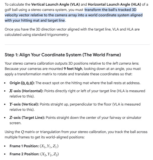
Note: the current CP method of VLA and HLA calculation already uses this same method as suggested by AI
AI says:
Complete C++ ImplementationThis function takes the world-space coordinates of the ball from two distinct frames and outputs the launch angles in degrees.cpp#include <iostream>
#include <cmath>
// Structure for 3D coordinates transformed to the hitting mat world frame
struct WorldPoint3D {
double x; // Left (-) / Right (+) relative to target line
double y; // Height above the ground
double z; // Distance downrange toward target
};
struct LaunchAngles {
double vla_deg; // Vertical Launch Angle in degrees
double hla_deg; // Horizontal Launch Angle in degrees
};
/**
* Calculates VLA and HLA from two consecutive world-coordinate points.
*/
LaunchAngles calculateLaunchAngles(const WorldPoint3D& p1, const WorldPoint3D& p2) {
// 1. Calculate direction vector components
double dx = p2.x - p1.x;
double dy = p2.y - p1.y;
double dz = p2.z - p1.z;
// Constants for radian-to-degree conversion
const double rad_to_deg = 180.0 / M_PI;
LaunchAngles angles;
// 2. Calculate Vertical Launch Angle (VLA)
// Horizontal ground distance traveled: sqrt(dx^2 + dz^2)
double ground_distance = std::sqrt(dx * dx + dz * dz);
angles.vla_deg = std::atan2(dy, ground_distance) * rad_to_deg;
// 3. Calculate Horizontal Launch Angle (HLA)
// Measures deviation along the X axis relative to the Z target line
angles.hla_deg = std::atan2(dx, dz) * rad_to_deg;
return angles;
}
int main() {
// Example: Ball launches from tee at (0, 0, 0)
WorldPoint3D frame1 = {0.0, 0.0, 0.0};
// Frame 2: Ball travels downrange (Z), climbs upward (Y), and pushes slightly right (X)
WorldPoint3D frame2 = {0.12, 0.45, 1.8};
LaunchAngles results = calculateLaunchAngles(frame1, frame2);
std::cout << "Vertical Launch Angle (VLA): " << results.vla_deg << " degrees" << std::endl;
std::cout << "Horizontal Launch Angle (HLA): " << results.hla_deg << " degrees" << std::endl;
std::cout << " (Positive HLA = Push/Right, Negative HLA = Pull/Left)" << std::endl;
return 0;
}
How to calculate ball speed from a stereo camera system
AI says:
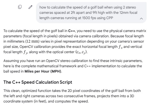
cpp#include <iostream>
#include <cmath>
// Structure to hold 3D coordinates in feet
struct Point3D {
double x; // Left/Right displacement
double y; // Up/Down displacement (relative to camera height)
double z; // Depth/Distance away from the camera plane
};
/**
* Calculates golf ball speed from two stereo frames.
*
* @param left_u1, left_v1 : Ball pixel coordinates in Left Camera (Frame 1)
* @param right_u1 : Ball X pixel coordinate in Right Camera (Frame 1)
* @param left_u2, left_v2 : Ball pixel coordinates in Left Camera (Frame 2)
* @param right_u2 : Ball X pixel coordinate in Right Camera (Frame 2)
* @param fx, fy : Focal lengths in pixels (from camera calibration)
* @param cx, cy : Optical center pixel coordinates (from camera calibration)
* @param baseline_ft : Distance between cameras in feet (2.0)
* @param fps : Camera frame rate (1500.0)
* @return : Speed in Miles per Hour (MPH)
*/
double calculateGolfBallSpeedMPH(
double left_u1, double left_v1, double right_u1,
double left_u2, double left_v2, double right_u2,
double fx, double fy, double cx, double cy,
double baseline_ft = 2.0, double fps = 1500.0)
{
// ----------------------------------------------------
// FRAME 1: Triangulate 3D Position
// ----------------------------------------------------
double disparity1 = left_u1 - right_u1;
if (disparity1 <= 0) return 0.0; // Avoid division by zero or negative depth
Point3D p1;
p1.z = (fx * baseline_ft) / disparity1;
p1.x = ((left_u1 - cx) * p1.z) / fx;
p1.y = ((left_v1 - cy) * p1.z) / fy;
// ----------------------------------------------------
// FRAME 2: Triangulate 3D Position
// ----------------------------------------------------
double disparity2 = left_u2 - right_u2;
if (disparity2 <= 0) return 0.0;
Point3D p2;
p2.z = (fx * baseline_ft) / disparity2;
p2.x = ((left_u2 - cx) * p2.z) / fx;
p2.y = ((left_v2 - cy) * p2.z) / fy;
// ----------------------------------------------------
// SPEED CALCULATION
// ----------------------------------------------------
// 1. Compute 3D Euclidian straight-line distance (feet)
double distance_ft = std::sqrt(
std::pow(p2.x - p1.x, 2) +
std::pow(p2.y - p1.y, 2) +
std::pow(p2.z - p1.z, 2)
);
// 2. Compute time difference between consecutive frames (seconds)
double delta_t = 1.0 / fps;
// 3. Compute speed in Feet per Second
double speed_fps = distance_ft / delta_t;
// 4. Convert Feet per Second to Miles per Hour (1 FPS = 0.681818 MPH)
double speed_mph = speed_fps * 0.681818;
return speed_mph;
}
int main() {
// --- Mock Calibration Data ---
// Example: A 1080p sensor where a 12mm lens yields fx/fy around 3600 pixels
double fx = 3600.0;
double fy = 3600.0;
double cx = 960.0; // Center X for 1920 width
double cy = 540.0; // Center Y for 1080 height
// --- Mock Tracking Data (Consecutive frames at 1500 FPS) ---
// Frame 1
double lu1 = 960.0, lv1 = 540.0;
double ru1 = 780.0; // Disparity = 180 pixels -> Depth = (3600*2)/180 = 40 feet
// Frame 2 (Ball moved slightly forward and to the right)
double lu2 = 980.0, lv2 = 535.0;
double ru2 = 798.5; // Disparity = 181.5 pixels -> Depth changes slightly
double speed = calculateGolfBallSpeedMPH(lu1, lv1, ru1, lu2, lv2, ru2, fx, fy, cx, cy);
std::cout << "Calculated Ball Speed: " << speed << " MPH" << std::endl;
return 0;
}
Critical C++ Architecture ConsiderationsSub-pixel Accuracy:
When tracking at \(1500\text{ FPS}\), the distance the ball travels between two single frames is tiny (a matter of inches).
If you only track the center of the ball to the nearest whole integer pixel, your speed calculation will violently jitter due to rounding errors.
Use an algorithm like Centroid Detection via Connected Components or Hough Circles to yield sub-pixel double floating-point coordinates.
Transforming to Ground Coordinates: The \[Y\] coordinate computed above is relative to the camera lenses (\(9\text{ ft}\) high).
If your camera array is tilted downward to face the hitting mat, you will need to multiply your Point3D coordinates by an Extrinsic Rotation Matrix (R) obtained
during your stereo setup calibration to align the \[Y\]-axis perfectly perpendicular to the floor.
Multi-Frame Smoothing: Relying on just two frames can introduce noise.
For production code, track the ball across 5 to 10 frames, compute the 3D position for each, and fit a 3D linear or parabolic regression line using a library like Eigen to calculate a highly accurate velocity vector.
Do you have your camera matrices/focal length in pixels already saved from an OpenCV calibration file, or do you need help writing the OpenCV code to load your XML/YML calibration file?
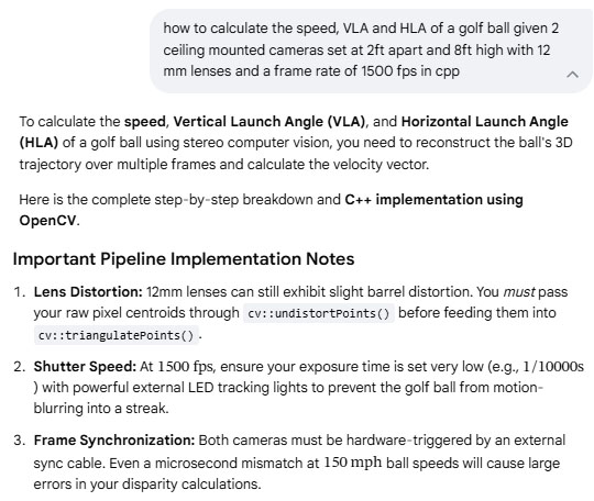
#include <iostream>
#include <cmath>
#include <vector>
#include <opencv2/opencv.hpp>
// Constants based on the user's physical setup
const double FPS = 1500.0;
const double DT = 1.0 / FPS; // Time between frames in seconds
const double BASELINE = 2.0; // 2 feet separation
struct Point3D {
double x, y, z;
};
struct BallMetrics {
double speed_fps; // Feet per second
double speed_mph; // Miles per hour
double vla_deg; // Vertical Launch Angle in degrees
double hla_deg; // Horizontal Launch Angle in degrees
};
// Function to calculate tracking metrics from two sequential 3D points
BallMetrics calculateGolfBallMetrics(const Point3D& p1, const Point3D& p2) {
double dx = p2.x - p1.x;
double dy = p2.y - p1.y;
double dz = p2.z - p1.z; // dz is negative if the ball goes UP (closer to ceiling)
// 3D Distance traveled
double distance = std::sqrt(dx*dx + dy*dy + dz*dz);
BallMetrics metrics;
metrics.speed_fps = distance / DT;
metrics.speed_mph = metrics.speed_fps * 0.681818; // Convert ft/s to mph
// Horizontal Launch Angle (relative to forward Y axis)
// Positive = Right, Negative = Left
metrics.hla_deg = std::atan2(dx, dy) * (180.0 / M_PI);
// Vertical Launch Angle (relative to the ground plane)
// We negate dz because a rising ball decreases its distance from the ceiling camera
double horizontal_dist = std::sqrt(dx*dx + dy*dy);
metrics.vla_deg = std::atan2(-dz, horizontal_dist) * (180.0 / M_PI);
return metrics;
}
int main() {
// 1. Stereo Calibration Setup (Replace placeholders with actual calibration values)
// Focal length 'f' must be in pixels (derived from calibration)
double f_pixel = 1500.0;
double cx = 640.0; // Principal point X
double cy = 480.0; // Principal point Y
// Projection matrices for Left and Right camera after stereoRectify()
cv::Mat P1 = (cv::Mat_<double>(3, 4) << f_pixel, 0, cx, 0,
0, f_pixel, cy, 0,
0, 0, 1, 0);
// Right camera is shifted by BASELINE (2.0 ft) along the X axis
cv::Mat P2 = (cv::Mat_<double>(3, 4) << f_pixel, 0, cx, -f_pixel * BASELINE,
0, f_pixel, cy, 0,
0, 0, 1, 0);
// 2. Simulated Ball Tracking Coordinates (2D Centroids from Left and Right frame matching)
// Frame T1
cv::Point2f left_pixel_t1(650.0f, 500.0f);
cv::Point2f right_pixel_t1(500.0f, 500.0f); // Disparity = 150
// Frame T2 (1/1500th of a second later)
cv::Point2f left_pixel_t2(665.0f, 485.0f);
cv::Point2f right_pixel_t2(520.0f, 485.0f); // Disparity = 145
// Container for triangulation
std::vector<cv::Point2f> left_pts = {left_pixel_t1, left_pixel_t2};
std::vector<cv::Point2f> right_pts = {right_pixel_t1, right_pixel_t2};
cv::Mat points4D;
// 3. Triangulate points to find 3D coordinates
cv::triangulatePoints(P1, P2, left_pts, right_pts, points4D);
// Extract Homogeneous coordinates back to 3D Cartesian coordinates
std::vector<Point3D> points3D(2);
for (int i = 0; i < 2; ++i) {
double w = points4D.at<float>(3, i);
points3D[i].x = points4D.at<float>(0, i) / w;
points3D[i].y = points4D.at<float>(1, i) / w;
points3D[i].z = points4D.at<float>(2, i) / w;
}
// 4. Calculate Final Launch Parameters
BallMetrics ball = calculateGolfBallMetrics(points3D[0], points3D[1]);
// Output Results
std::cout << "--- Golf Ball Launch Monitor Results ---" << std::endl;
std::cout << "Ball Speed: " << ball.speed_fps << " ft/s (" << ball.speed_mph << " mph)" << std::endl;
std::cout << "Vertical Launch Angle (VLA): " << ball.vla_deg << " degrees" << std::endl;
std::cout << "Horizontal Launch Angle (HLA): " << ball.hla_deg << " degrees" << std::endl;
return 0;
}
How to calibrate the cameras using OpenCV
Note: the current CP method of camera calibration uses a tried and tested calibration table that seems to work just fine,
so I'll have to compare it with the AI method to see if it is worth updating.
AI says:
To perform camera calibration in OpenCV, you must capture multiple images of a known pattern
(typically a chessboard or an asymmetric circle grid) from different angles.
OpenCV uses these images to solve for the camera's intrinsic parameters (focal length, optical center) and distortion coefficients (radial and tangential lens distortion).
Here is the complete workflow and C++ code using OpenCV 4.x to calibrate a camera and save the parameters to a file.
Step 1: Collect Your Calibration DataPrint a high-quality chessboard pattern and glue it to a perfectly flat surface (rigid cardboard or wood).Count the number of inner corners (where black and white squares meet).
For example, a standard 9x7 square board has 8x6 inner corners
.Measure the exact physical size of one square side (e.g., in millimeters or feet).Capture 15 to 30 images of the chessboard from different distances, angles, and tilt orientations, making sure the board covers all regions of the frame (especially the edges).
Step 2: The C++ Calibration ScriptThis production-grade script will read calibration images from a directory, detect the corners, compute the camera matrix, and save the result to a .yml file.
cpp
#include <iostream>
#include <vector>
#include <string>
#include <opencv2/opencv.hpp>
#include <opencv2/core/utils/filesystem.hpp>
int main() {
// ----------------------------------------------------
// 1. CONFIGURATION
// ----------------------------------------------------
// Define the number of INNER corners of the chessboard (Columns x Rows)
cv::Size board_size(8, 6);
float square_size_mm = 25.0f; // Exact size of one square edge in mm
std::string image_dir = "./calibration_images/";
std::string output_file = "camera_calibration.yml";
// ----------------------------------------------------
// 2. PREPARE 3D OBJECT POINTS
// ----------------------------------------------------
// These are the real-world 3D coordinates of the corners, assuming Z=0
std::vector<cv::Point3f> object_points_3d;
for (int i = 0; i < board_size.height; ++i) {
for (int j = 0; j < board_size.width; ++j) {
object_points_3d.push_back(cv::Point3f(j * square_size_mm, i * square_size_mm, 0.0f));
}
}
std::vector<std::vector<cv::Point3f>> object_points; // 3D points container
std::vector<std::vector<cv::Point2f>> image_points; // 2D pixel points container
// ----------------------------------------------------
// 3. READ IMAGES AND DETECT CHESSBOARD CORNERS
// ----------------------------------------------------
std::vector<cv::String> image_files;
cv::utils::fs::glob(image_dir, "*.jpg", image_files); // Supports .jpg, modify if needed
if (image_files.empty()) {
std::cerr << "Error: No images found in " << image_dir << std::endl;
return -1;
}
cv::Size img_size;
for (const auto& file_path : image_files) {
cv::Mat img = cv::imread(file_path);
if (img.empty()) continue;
img_size = img.size();
cv::Mat gray;
cv::cvtColor(img, gray, cv::COLOR_BGR2GRAY);
std::vector<cv::Point2f> corner_pixels;
// Find rough corner locations
bool found = cv::findChessboardCorners(gray, board_size, corner_pixels,
cv::CALIB_CB_ADAPTIVE_THRESH + cv::CALIB_CB_NORMALIZE_IMAGE + cv::CALIB_CB_FAST_CHECK);
if (found) {
// Refine the corner locations to sub-pixel accuracy (Crucial for high-speed tracking!)
cv::cornerSubPix(gray, corner_pixels, cv::Size(11, 11), cv::Size(-1, -1),
cv::TermCriteria(cv::TermCriteria::EPS + cv::TermCriteria::COUNT, 30, 0.001));
// Optional: Draw and display the detected corners for verification
// cv::drawChessboardCorners(img, board_size, corner_pixels, found);
// cv::imshow("Corners", img);
// cv::waitKey(100);
image_points.push_back(corner_pixels);
object_points.push_back(object_points_3d);
} else {
std::cout << "Warning: Chessboard corners not found in " << file_path << std::endl;
}
}
// ----------------------------------------------------
// 4. PERFORM CAMERA CALIBRATION
// ----------------------------------------------------
cv::Mat camera_matrix = cv::Mat::eye(3, 3, CV_64F);
cv::Mat dist_coeffs = cv::Mat::zeros(8, 1, CV_64F); // Supports up to 8 coefficients
std::vector<cv::Mat> rvecs, tvecs;
std::cout << "Calibrating camera with " << image_points.size() << " frames..." << std::endl;
double rms = cv::calibrateCamera(object_points, image_points, img_size,
camera_matrix, dist_coeffs, rvecs, tvecs);
std::cout << "Calibration complete. Root Mean Square (RMS) Error: " << rms << " pixels" << std::endl;
std::cout << "An RMS error < 0.5 is ideal. If > 1.0, recalibrate with better images." << std::endl;
// ----------------------------------------------------
// 5. SAVE CALIBRATION PARAMETERS TO DISK
// ----------------------------------------------------
cv::FileStorage fs(output_file, cv::FileStorage::WRITE);
if (fs.isOpened()) {
fs << "image_width" << img_size.width;
fs << "image_height" << img_size.height;
fs << "camera_matrix" << camera_matrix;
fs << "distortion_coefficients" << dist_coeffs;
fs.release();
std::cout << "Calibration data successfully saved to: " << output_file << std::endl;
} else {
std::cerr << "Error: Could not open output file to save parameters." << std::endl;
}
return 0;
}
Step 3:
Extracting Parameters for Your Stereo Speed AppOnce this script runs, opening camera_calibration.yml will reveal a layout resembling the following data structure:yamlcamera_matrix: !!opencv-matrix
rows: 3
cols: 3
dt: d
data: [ 3.6045e+03, 0.0000e+00, 9.6023e+02,
0.0000e+00, 3.6031e+03, 5.4011e+02,
0.0000e+00, 0.0000e+00, 1.0000e+00 ]
Use code with caution.From this matrix:fx = 3604.5 (Row 1, Col 1) — This is the horizontal pixel focal length for your 12mm lens.fy = 3603.1 (Row 2, Col 2) — Vertical pixel focal length.cx = 960.23 (Row 1, Col 3) — Optical center X axis.cy = 540.11 (Row 2, Col 3) — Optical center Y axis.These are the exact numerical values required by your velocity algorithm script.Next Step: Stereo CalibrationBecause you are tracking a ball in 3D using two separate cameras, individual standalone calibration is only the baseline step. You must ultimately execute cv::stereoCalibrate() passing image inputs simultaneously recorded by both your Left and Right cameras. This generates a Rotation Matrix (R) and a Translation Vector (T) mapping the exact rigid 3D spatial alignment between the two cameras.Would you like the corresponding C++ script to run cv::stereoCalibrate() using paired Left and Right camera images, or do you need help writing code to undistort the raw camera frames before passing them to your tracking algorithm?
C++ Stereo Calibration Scriptcpp#include <iostream>
#include <vector>
#include <string>
#include <opencv2/opencv.hpp>
#include <opencv2/core/utils/filesystem.hpp>
int main() {
// ----------------------------------------------------
// 1. CONFIGURATION
// ----------------------------------------------------
cv::Size board_size(8, 6); // Inner corners of the chessboard (Cols x Rows)
float square_size_ft = 0.082f; // Size of one square edge in feet (approx 25mm = 0.082 ft)
// Note: Calibrating directly in feet makes your 3D outputs match your baseline!
std::string left_dir = "./stereo_images/left/";
std::string right_dir = "./stereo_images/right/";
std::string output_file = "stereo_calibration.yml";
// ----------------------------------------------------
// 2. PREPARE 3D OBJECT POINTS
// ----------------------------------------------------
std::vector<cv::Point3f> object_points_3d;
for (int i = 0; i < board_size.height; ++i) {
for (int j = 0; j < board_size.width; ++j) {
object_points_3d.push_back(cv::Point3f(j * square_size_ft, i * square_size_ft, 0.0f));
}
}
std::vector<std::vector<cv::Point3f>> object_points;
std::vector<std::vector<cv::Point2f>> image_points_L;
std::vector<std::vector<cv::Point2f>> image_points_R;
// ----------------------------------------------------
// 3. READ PAIRED IMAGES & DETECT CORNERS
// ----------------------------------------------------
std::vector<cv::String> left_files, right_files;
cv::utils::fs::glob(left_dir, "*.jpg", left_files);
cv::utils::fs::glob(right_dir, "*.jpg", right_files);
if (left_files.size() != right_files.size() || left_files.empty()) {
std::cerr << "Error: Image counts do not match or directories are empty!" << std::endl;
return -1;
}
cv::Size img_size;
for (size_t i = 0; i < left_files.size(); ++i) {
cv::Mat img_L = cv::imread(left_files[i], cv::IMREAD_GRAYSCALE);
cv::Mat img_R = cv::imread(right_files[i], cv::IMREAD_GRAYSCALE);
if (img_L.empty() || img_R.empty()) continue;
img_size = img_L.size();
std::vector<cv::Point2f> corners_L, corners_R;
// Find corners in both left and right frames
bool found_L = cv::findChessboardCorners(img_L, board_size, corners_L,
cv::CALIB_CB_ADAPTIVE_THRESH + cv::CALIB_CB_NORMALIZE_IMAGE);
bool found_R = cv::findChessboardCorners(img_R, board_size, corners_R,
cv::CALIB_CB_ADAPTIVE_THRESH + cv::CALIB_CB_NORMALIZE_IMAGE);
// BOTH cameras must see the chessboard in the same frame pair
if (found_L && found_R) {
cv::cornerSubPix(img_L, corners_L, cv::Size(11, 11), cv::Size(-1, -1),
cv::TermCriteria(cv::TermCriteria::EPS + cv::TermCriteria::COUNT, 30, 0.001));
cv::cornerSubPix(img_R, corners_R, cv::Size(11, 11), cv::Size(-1, -1),
cv::TermCriteria(cv::TermCriteria::EPS + cv::TermCriteria::COUNT, 30, 0.001));
image_points_L.push_back(corners_L);
image_points_R.push_back(corners_R);
object_points.push_back(object_points_3d);
}
}
std::cout << "Extracted " << image_points_L.size() << " valid stereo image pairs." << std::endl;
// ----------------------------------------------------
// 4. RUN STEREO CALIBRATION
// ----------------------------------------------------
// Initialize matrices (will be populated by the calibration function)
cv::Mat M1 = cv::Mat::eye(3, 3, CV_64F); // Left Camera Intrinsic Matrix
cv::Mat D1 = cv::Mat::zeros(5, 1, CV_64F); // Left Camera Distortion
cv::Mat M2 = cv::Mat::eye(3, 3, CV_64F); // Right Camera Intrinsic Matrix
cv::Mat D2 = cv::Mat::zeros(5, 1, CV_64F); // Right Camera Distortion
cv::Mat R, T, E, F; // Extrinsic outputs (Rotation, Translation, Essential, Fundamental)
std::cout << "Calibrating stereo setup... This may take a moment." << std::endl;
// We let OpenCV calibrate the intrinsics and extrinsics simultaneously
double rms = cv::stereoCalibrate(
object_points, image_points_L, image_points_R,
M1, D1, M2, D2, img_size, R, T, E, F,
cv::CALIB_FIX_ASPECT_RATIO + cv::CALIB_SAME_FOCAL_LENGTH,
cv::TermCriteria(cv::TermCriteria::COUNT + cv::TermCriteria::EPS, 100, 1e-5)
);
std::cout << "Stereo Calibration Complete!" << std::endl;
std::cout << "Stereo RMS Error: " << rms << " pixels (Target: < 0.5)" << std::endl;
// ----------------------------------------------------
// 5. COMPUTE STEREO RECTIFICATION (Crucial for Speed Tracking)
// ----------------------------------------------------
// This aligns the vertical rows of both cameras so that a point in the
// left camera resides on the exact same row (Y coordinate) in the right camera.
cv::Mat R1, R2, P1, P2, Q;
cv::stereoRectify(M1, D1, M2, D2, img_size, R, T, R1, R2, P1, P2, Q, cv::CALIB_ZERO_DISPARITY, -1, img_size);
// ----------------------------------------------------
// 6. SAVE PARAMETERS TO FILE
// ----------------------------------------------------
cv::FileStorage fs(output_file, cv::FileStorage::WRITE);
if (fs.isOpened()) {
fs << "M1" << M1 << "D1" << D1; // Left Camera Profile
fs << "M2" << M2 << "D2" << D2; // Right Camera Profile
fs << "R" << R << "T" << T; // Spatial relationship
fs << "R1" << R1 << "R2" << R2; // Rectification transformations
fs << "P1" << P1 << "P2" << P2; // Projection matrices
fs << "Q" << Q; // Disparity-to-depth mapping matrix
fs.release();
std::cout << "Stereo configuration parameters written to: " << output_file << std::endl;
}
return 0;
}
How to integrate real-time AI into an application
As to whether or not real-time AI integration is going to be significantly better than using the AI generated code applied directly into the CP application remains to be seen.
My fear is that sending images to AI for analysis and waiting for a result may take too long when used in a real-time application
AI says:
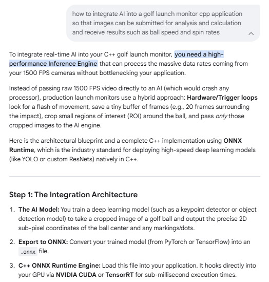
Step 2:
C++ Integration Implementation
This production-ready wrapper class initializes the AI engine, preprocesses raw camera frames (converting cv::Mat to raw tensors), runs real-time inference, and extracts the ball metrics.cpp#include <iostream>
#include <vector>
#include <string>
#include <numeric>
#include <opencv2/opencv.hpp>
#include <onnxruntime_cxx_api.h> // Core ONNX Runtime API
class GolfLaunchMonitorAI {
private:
Ort::Env env;
std::unique_ptr<Ort::Session> session;
Ort::MemoryInfo memory_info;
// Model configurations
const int input_width = 224;
const int input_height = 224;
const int channels = 3;
const size_t input_tensor_size = channels * input_width * input_height;
std::vector<int64_t> input_shape = {1, channels, input_height, input_width};
std::vector<const char*> input_names = {"input_images"};
std::vector<const char*> output_names = {"ball_metrics"}; // Outputs: [center_x, center_y, dot_x, dot_y]
public:
GolfLaunchMonitorAI(const std::string& model_path)
: env(ORT_LOGGING_LEVEL_WARNING, "GolfMonitor"),
memory_info(Ort::MemoryInfo::CreateCpu(OrtAllocatorType::OrtArenaAllocator, OrtMemType::OrtMemTypeDefault))
{
// 1. Configure Session Options for Maximum Real-Time Speed
Ort::SessionOptions session_options;
session_options.SetIntraOpNumThreads(4); // Match your CPU physical cores
session_options.SetGraphOptimizationLevel(GraphOptimizationLevel::ORT_ENABLE_ALL);
// Optional: Enable NVIDIA CUDA GPU Acceleration if available
// OrtSessionOptionsAppendExecutionProvider_CUDA(session_options, 0);
// 2. Load the compiled AI Model
session = std::make_unique<Ort::Session>(env, model_path.c_str(), session_options);
std::cout << "�� AI Inference Engine successfully initialized!" << std::endl;
}
/**
* Preprocesses a raw OpenCV crop frame into a normalized CHW tensor
*/
void preprocess(const cv::Mat& src, std::vector<float>& output_tensor) {
cv::Mat resized, floated;
cv::resize(src, resized, cv::Size(input_width, input_height));
resized.convertTo(floated, CV_32FC3, 1.0 / 255.0); // Normalize pixels to [0, 1]
// Convert OpenCV HWC (Height, Width, Channels) to Deep Learning CHW format
output_tensor.resize(input_tensor_size);
std::vector<cv::Mat> chw_channels(3);
chw_channels[0] = cv::Mat(input_height, input_width, CV_32FC1, &output_tensor[0]);
chw_channels[1] = cv::Mat(input_height, input_width, CV_32FC1, &output_tensor[input_width * input_height]);
chw_channels[2] = cv::Mat(input_height, input_width, CV_32FC1, &output_tensor[input_width * input_height * 2]);
cv::split(floated, chw_channels);
}
/**
* Evaluates a stereo frame pair to track sub-pixel coordinates
* Outputs coordinates relative to the original image scale
*/
cv::Point2f analyzeFrame(const cv::Mat& raw_frame) {
std::vector<float> input_tensor_values;
preprocess(raw_frame, input_tensor_values);
// 3. Create ORNX Input Tensors
Ort::Value input_tensor = Ort::Value::CreateTensor<float>(
memory_info, input_tensor_values.data(), input_tensor_values.size(),
input_shape.data(), input_shape.size()
);
// 4. Run AI Inference (Typically takes 1-5 milliseconds)
auto output_tensors = session->Run(
Ort::RunOptions{nullptr},
input_names.data(), &input_tensor, 1,
output_names.data(), 1
);
// 5. Extract results
float* output_data = output_tensors.front().GetTensorMutableData<float>();
// Assuming your network outputs normalized [0, 1] relative coordinates
float detected_x = output_data[0] * raw_frame.cols;
float detected_y = output_data[1] * raw_frame.rows;
return cv::Point2f(detected_x, detected_y);
}
};
// ----------------------------------------------------
// APPLICATION HIERARCHY / PIPELINE MAIN
// ----------------------------------------------------
int main() {
// Instantiate AI tracking module
GolfLaunchMonitorAI ai_engine("models/golf_ball_tracker.onnx");
// Mock incoming frames from camera hardware buffer (Frame 1 & Frame 2)
cv::Mat left_camera_frame1 = cv::imread("data/left_f1.jpg");
cv::Mat right_camera_frame1 = cv::imread("data/right_f1.jpg");
cv::Mat left_camera_frame2 = cv::imread("data/left_f2.jpg");
cv::Mat right_camera_frame2 = cv::imread("data/right_f2.jpg");
if(left_camera_frame1.empty()) {
std::cerr << "Could not read mock image data." << std::endl;
return -1;
}
// Pass frames to AI to extract high-precision tracking locations
cv::Point2f ball_L1 = ai_engine.analyzeFrame(left_camera_frame1);
cv::Point2f ball_R1 = ai_engine.analyzeFrame(right_camera_frame1);
cv::Point2f ball_L2 = ai_engine.analyzeFrame(left_camera_frame2);
cv::Point2f ball_R2 = ai_engine.analyzeFrame(right_camera_frame2);
std::cout << "\n--- AI Tracking Results ---" << std::endl;
std::cout << "Frame 1 Left Pixel: (" << ball_L1.x << ", " << ball_L1.y << ")" << std::endl;
std::cout << "Frame 1 Right Pixel: (" << ball_R1.x << ", " << ball_R1.y << ")" << std::endl;
// Next: Feed these highly accurate coordinates directly into your previously
// implemented math calculations (Stereo Triangulation -> Speed -> Spin rates -> VLA/HLA)
return 0;
}

 Home
Home Products
 Cameras
 Software
 Enclosures
 ProTee
 E6 Courses
 Business
 Tech News
 View Cart