![]()
![]()

Installation
![]()
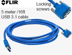
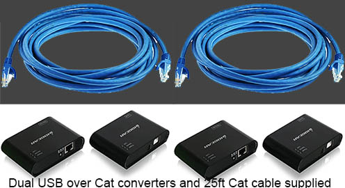
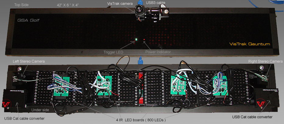
Camera wiring
 -
-


Installing the Control Panel software.
For new installations, download and run the following programs and files
GSA Control Panel (CP) full version download
V.9.3.0.0 April 2 2020
After you have downloaded and installed the full version GSA Control Panel, download and install the below GSA Golf Control Panel update

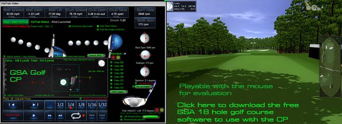
GSA Golf Game software download
Note: If you encounter a windows error message stating that it could not find d3dx9_30.dll when starting GSA Golf,
download and copy the d3dx9_30.dll to your windows\SysWOW64 folder.
Download here d3dx9_30.dll
![]()
E6 Connect download

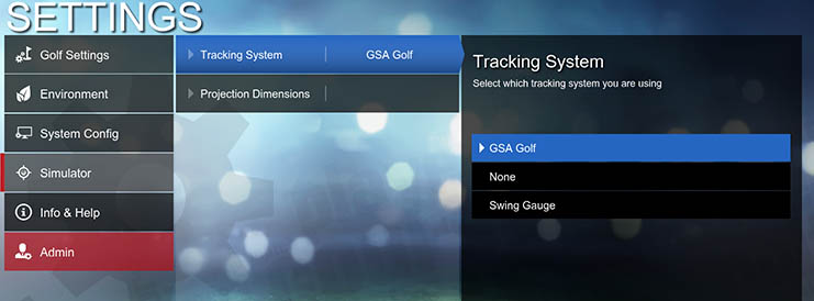
Select GSA Golf in the Settings / Simulator options
 -
-
Select E6 CONNECT in the GSA Golf Control Panel's main window
![]()
Error message when first starting the CP ?
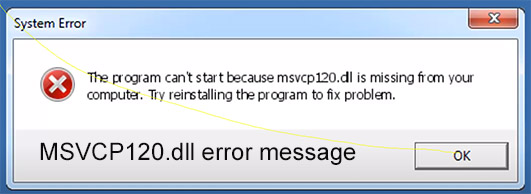
If you see the above error message when first starting the Control Panel (CP)
then your PC requires the VC Redistributable files.
Click on the above image to see an installation video
Download VC redistributables hereHere
Installing the Camera driver software
GSA Golf camera Viewer and driver software
Camera Driver 2.11 33MB
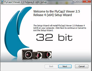
Click above to download and install the Camera FlyCap2 Viewer application
The app is located in the
C:\Program Files (x86)\Point Grey Research\FlyCap2 Viewer\bin folder
and is called Point Grey FlyCap2
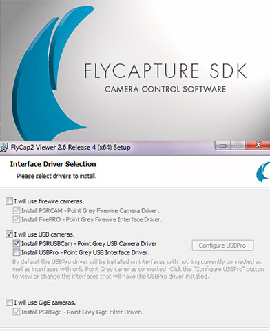
Select "I will use USB cameras" and select "Install PGRUSBCam driver" when prompted.
Important ! Do not select the "USBPro" option !
If you have previously run this install program and think you may have selected the USBPro option then you must uninstall the FlyCapture Viewer and re-run it
![]()
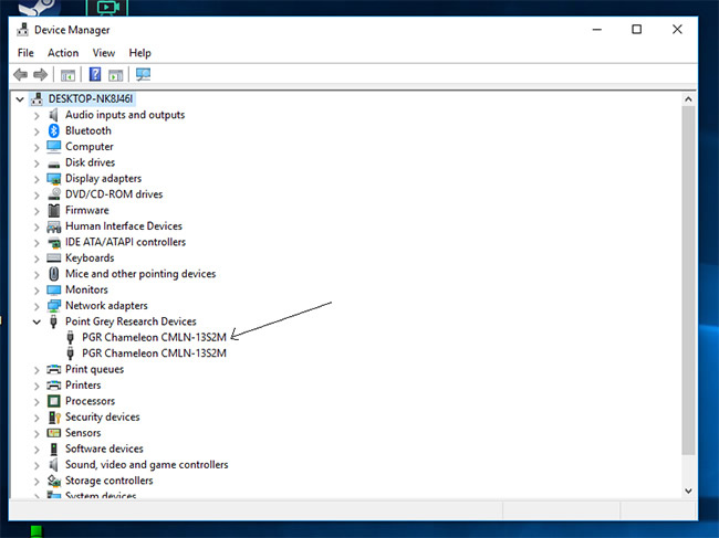
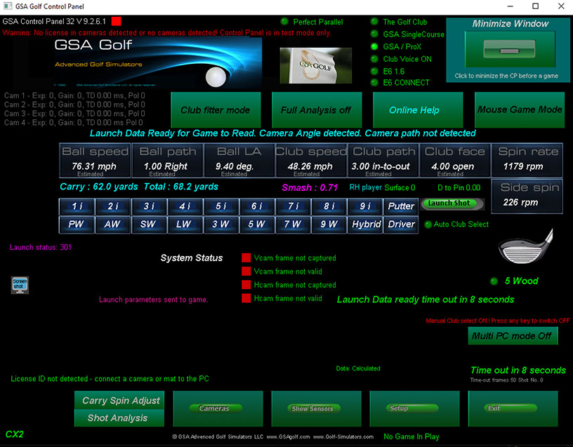
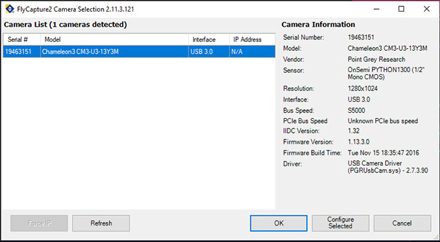
Once the drivers are installed and the cameras connected to the PC you should see in the Windows Device Manager that the cameras are detected as PGR cameras.
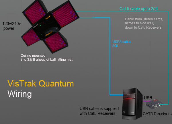
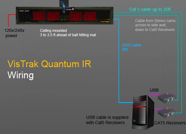
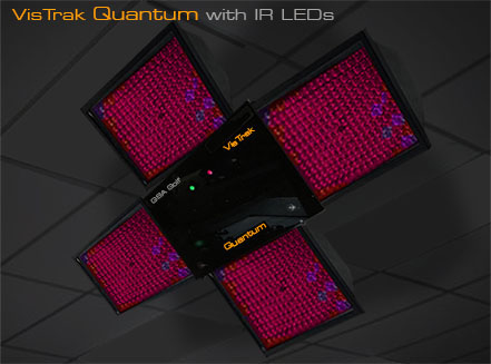
VisTrak Quantum Mounting
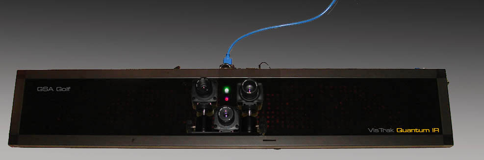
-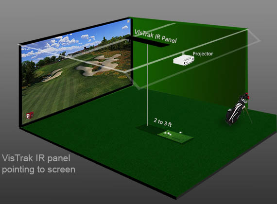

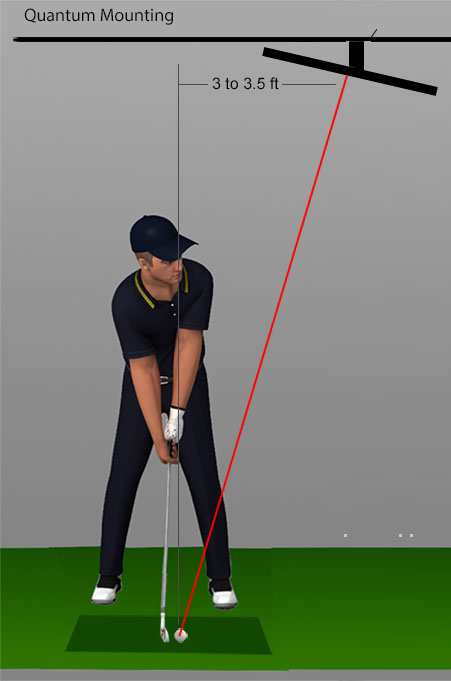
Use the ball swivel joint on the Projector mount to angle the Quantum directly
at the place where you will be playing the ball from.
Mounting the IR LED lamps
If not using the Quantum IR with built in IR LED lighting,
then 4 individual LED lamps should be mounted either around the Quantum unit
or somewhere close to it.
Aim all 4 lamps directly towards the hitting mat.
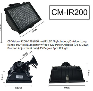
Note: If you have purchased the Quantum without IR LED lighting, then the recommended IR light is the CM vision 200.
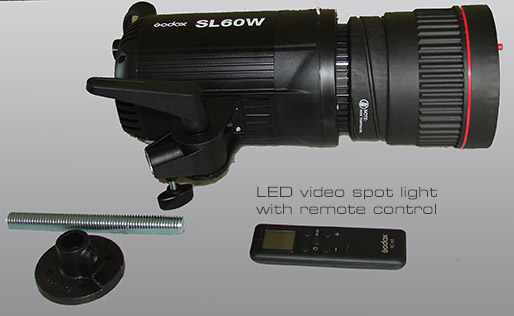
You can also use a single visible light spotlight like the SL60W
Either way, strong lighting is required to run the hi-speed VisTrak camera.
Confirm that the cameras are running
Before connecting the cameras to the PC, first start the CP without any cameras connected.
Go to the Setup window and select the product your are using.
In this case, "VisTrak Qauntum Lite".
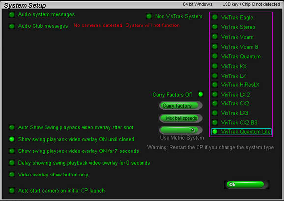
Then go the cameras window and ensure that the options "Fixed Assigns" is OFF

Then shut down the CP, connect the cameras and re-start the CP.
In the case of the Quantum Lite, you should see the message "cameras 1 and 2 Running".
Then go to the "Cameras" window from the main window.
To confirm that the cameras are operational, select the "Video Stream Mode"
or click the "Soft Trigger" button in the Camera window.
You should then see that new images are being grabbed and displayed
Go to the Cameras window in the CP and click the "Video Stream Mode" option ON
Place a ball in the usual striking position on the mat and adjust the camera's aim so that
the ball appears more or less in the center of the image.
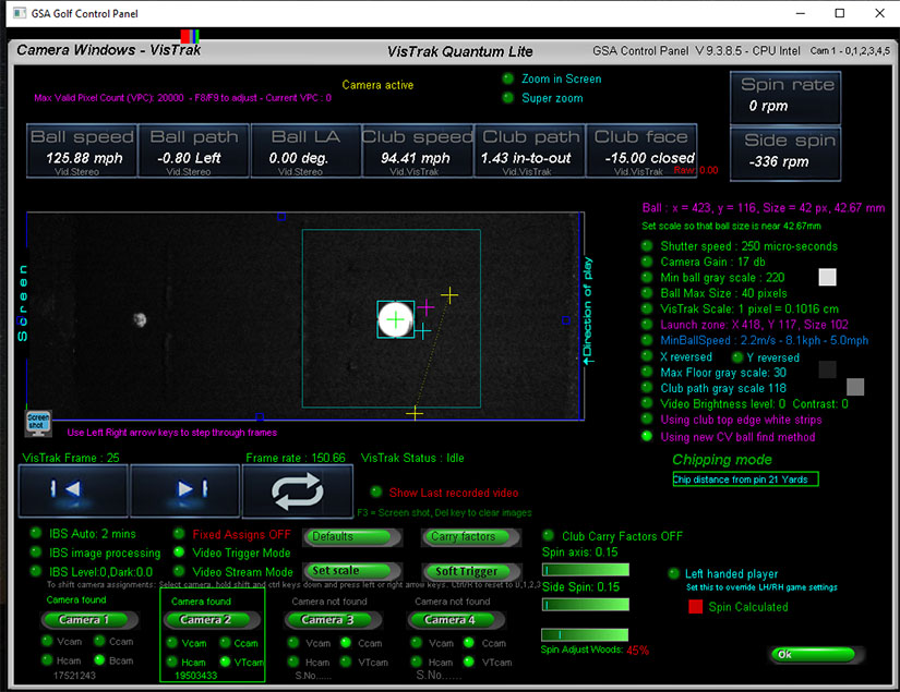
Camera Assignments

If you see the above warning message in the camera windows, then the camera assignments are not correct.
With the Quantum Lite or VisTrak IRVC, camera 1 is the ball launch angle camera and camera 2 is the VisTrak camera.
With the Quantum standard , camera 1 is the ball launch angle camera, camera 2 is the ball spin camera and camera 3 is the VisTrak camera.
Follow the above instructions to re-assign the cameras to their correct positions.
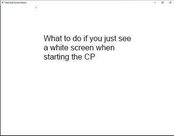
If the camera assignments aren't correct, then the CP may hang and just show a white screen when started.
To fix:
1. unplug all cameras from the PC.
2. restart the CP and switch the "Fixed Assigns" option OFF.
3. shut the CP down.
4. plug the cameras back into the PC and restart the CP.
5. Check that assignments are correct.
If it's a 2 camera system, then camera 1 is the Vcam camera and 2 is the VisTrak camera.
If it's a 3 camera system, then camera 1 is the Vcam camera, camera 2 the Hcam camera and 3 is the VisTrak camera.
If re-assigning cameras then the "Fixed Assigns" should be switched back ON again and the CP re-started
Aiming the cameras

Note that all cameras on the Quantum IR are already externally mounted
![]()
All the Quantum cameras should be aimed at the hitting mat so that the ball - in its regullar hitting position -
appears more or less in the center of the images.
Camera 1 with the Quantum Lite is the ball launch angle camera.
Camera 2 with the Quantum Lite is the hi-speed VisTrak camera.
With the Quantum Lite, Camera 1 is fixed to the casing frame bracket and camera 2 (the VisTrak camera) is mounted on ball a swivel joint.
Select camera 1 and select "Video Stream Mode".
Place a ball on the mat in its regular hitting position.
Use the projector mount swivel ball joint to aim the camera and casing to the ball on the hitting mat so that it appears in the center of the image.
Then select camera 2 and also select "Video Stream Mode".
Using the camera swivel ball joint, again aim the camera to the ball on the hitting mat so that it appears in the center of the image.
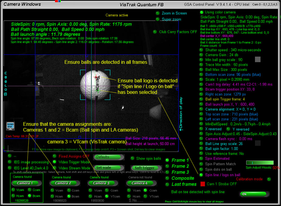
Quantum FB
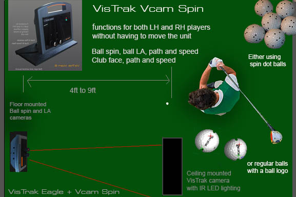
Testing the cameras
Cameras 1 and 2 with the Quantum FB are the floor mounted LA/Ball spin spin cameras.
Camera 3 is the ceiling mounted VisTrak camera.
Ensure that the cameras are correctly assigned to this sequence.
To test the cameras, left click on the "Soft Trigger" a new frame in cameras 1 and 2 windows of the CP.
The images captured will probably be rather dark as regular camera soft triggers won't fire the IR Xenon flashes.
Right click on the "Soft Trigger" button in both cameras to send a hard trigger signal to the cameras
so that the flash units fire and you get bright images.
Quantum FB

Running the system
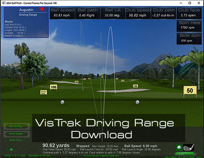
Click on the above links to read how to run and operate the VisTrak system.
Note: the only difference between the VisTrak Eagle and the Quantum Lite, is the addition of the ball launch angle camera,
so the operation is essentially the same.
And the only difference between the Quantum Lite and the regular Quantum, is the addition of the ball spin camera,
so the operation is also essentially the same.
Principle of Operation
VisTrak Quantum physics : Spin rate and spin axis theory
Measuring spin rate from an overhead camera system using spin dot balls
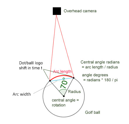
A little math is required to deduce the spin rate from the circle arc measured from the rotating and shifting key point pattern on the ball.
Knowing the circle arc length (i.e. the vertical shift of the key point pattern on the ball as viewed from above) and the radius of the ball, the arc central angle can be calculated.
This arc central angle is the rotation in degrees (or radians) for a given time between the two frames (1 ms) and from this, the spin rate can be calculated.
VisTrak Quantum data capturing method
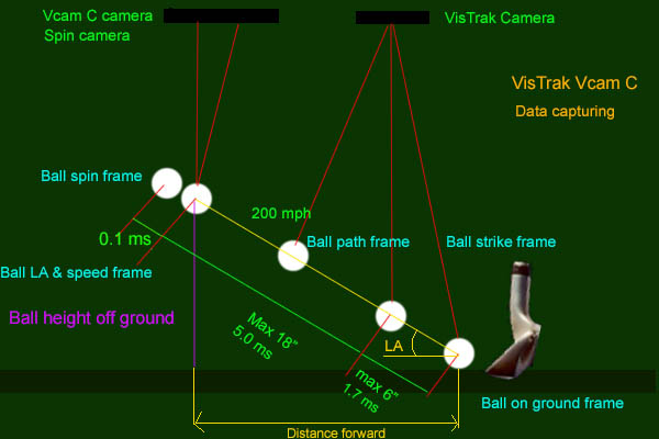
1. The VisTrak camera detects when a ball is placed in the launch zone area
2. When a ball is detected, the stereo cameras are triggered to grab frames of the ball at the launch position.
3. The VisTrak camera is then placed in full speed mode (590 fps) while constantly checking to see if the ball moves forward.
4. As soon as the ball moves, (strike frame) a trigger signal is sent (via a GPIO line) to the stereo cameras
5. The stereo cameras are programmed to delay any trigger signal by 5 milli-seconds and 5.1 ms
6. The Stereo cameras then detect the height the ball is off the ground and calculates the launch angle and the spin rate based on the ball's rotation within 0.1 ms
7. The ball path - left or right - is detected by the VisTrak camera as is the club speed, face angle and club path
8. The ball speed is then calculated from the distance the ball has traveled from the ball strike frame in the VisTrak camera and the ball's position in the stereo cameras.
Notes:
While the camera's GPIO trigger signal is very fast (just a few nano seconds), there can be up to a 1.7 ms delay (1/590 frame rate) for the VisTrak camera to detect ball movement.
At a speed of 200 mph - and in a worst case - the ball may have already traveled some 6 inches before movement had been detected.
This distance has to be taken into account when measuring how far the ball has traveled within the 5 ms time frame in order to accurately measure ball speed.
After all these operations, a final check is made to see if the data is valid and that the ball's movement extended outside the launch zone.
i.e. it wasn't just a re-positioning of the ball on the hitting mat or from an inadvertent ball contact from a club waggle (or the ball just fell off the tee).
Calculating ball speed, LA and path
While the VisTrak hi-speed camera in the Quantum measures club data, the high resolution camera(s) measure ball Launch angle, speed and path
plus ball spin for full version Quantum systems.
In order to do so, the scaling factor has to be correctly set.
Setting the scaling factor:
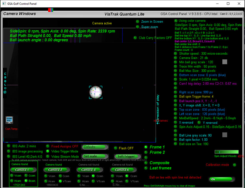
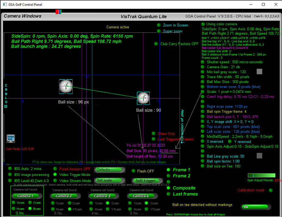
Select camera 1 and place a ball on the mat and hit the "Soft Trigger" to grab a new frame.
The camera will then detect the ball and measure its size. In the above example, the ball size is 90 pixels.
Select the "Scale" factor and set its value so that the "ball size" in cm is close to 42.67 mm which is the diameter of a golf ball.
Measuring ball launch angle
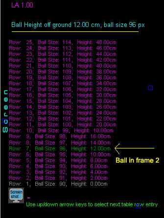
The LA camera in the Quantum system grabs two frames. One of the ball on the floor before ball strike and another of the ball in flight after a certain time period.
Ball Launch angle is calculated by converting the ball image size to ball height off the ground.
A user adjustable ball-image-size to ball-height-off the ground table is used for this.
In order to measure ball LA correctly, the table has to initialized to suit the users camera mounting height off the ground.
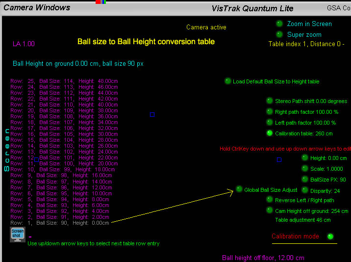
Setting the ball size to ball height table
Select camera 1 and place a ball on the mat and hit the "Soft Trigger" to grab a new frame. Note the size of the ball image.
Select the "Calibration Mode" option in camera 1 to show the conversion table.
All that needs to be done is to set the ball size for a height of 0 cm based on the ball image size measured at ground level.
To do this, use the "Global Ball Size Adjust" option and press the Up/Down keyboard arrow keys until the ball size measured is visible on Row 1 of the table.
e.g. if your measured ball size of the ball at ground level is 90 pixels, then press the down arrow key until 90px is shown at row 1. (which is the zero height position).
Note: if you don't see any values in the table then press the "Load default ball size to height table" button.
At a later date you can also adjust individual entries in the table for fine adjustment.
Note: An automated method of initializing the table will be available soon.
Setting the LA and Ball spin camera Trigger Delays.
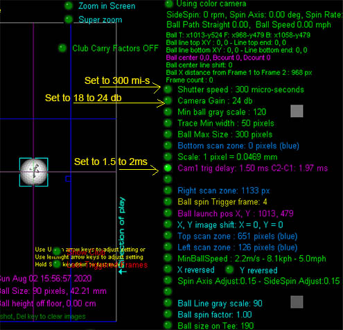
The camera trigger delay is used to delay the camera trigger from the VisTrak camera so that the ball has time to travel before an image of it in flight is grabbed.
The trigger signal from the VisTrak camera is sent out as soon as the club strikes the ball, so unless there's a trigger delay, the ball will always appear next to the club.
Other important settings are the camera's Shutter speed and Gain values.
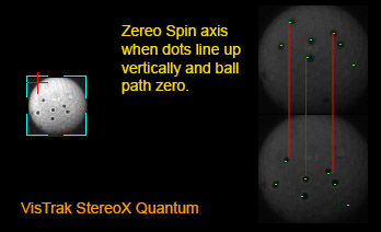
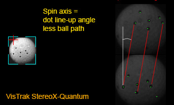
Ball spin detection
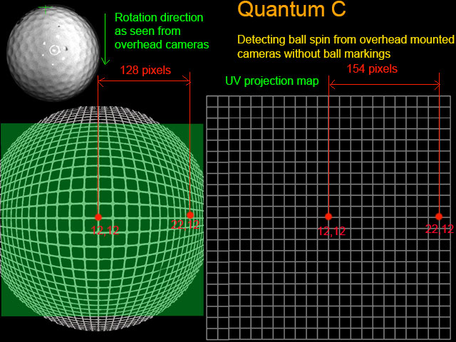
Detecting ball spin from ceiling mounted cameras that look down on the ball, requires a different approach.
When looking down on the ball, back spin rotation will appear as image shift downwards and not as regular rotation as when the cameras are viewing the ball from the side.
As the ball is spherical, images of the dimple patterns are distorted as the ball rotates, so that direct dimple pattern matching of two images of the ball will not be possible.
The above method solves this problem by projecting the ball's 3D spherical surface onto a 2D UV map so that dimple spin patterns are not distorted during the rotation
and thus can be located and matched.
As we are only seeing a small arc of the rotation, camera frame timing must be very fast. Currently, a frame time of 0.2 ms or 200 micro seconds is being used.
Using two individual hi-resolution cameras that only grab 1 image of the ball each, we can set the frame timing to be as fast as we want.
At a 1 milli-second frame time, the dual camera system has the equivalent of a 1000 fps camera and at 0.2 ms, the camera system will have
the equivalent of a 5000 frames per second camera.
Not bad for a low cost system we think.
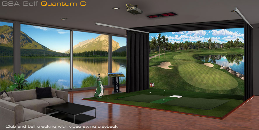
The Quantum C will undoubtedly be our best selling system by far, and it's price -
compared to the competition that are in the $10,000 to $20,000 range - should ensure that it dominates the market.
Data captured: Ball spin and spin axis, ball speed, LA and path, club face, club speed and path with swing video playback .
Beta version now available without ball spin software - free ball spin software updates available as of September 21.
Estimated final release date : October 15 2020.
Related Tech help links
 -
- -
-
 -
-

![]()
![]()
 Home
Home Products
 Cameras
 Software
 Enclosures
 GSA Courses
 E6 Courses
 Business
 Tech News